


Heat & Glo • Everest • 750-900 Rev. o • 10/08
17
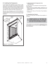
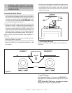
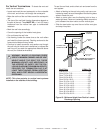
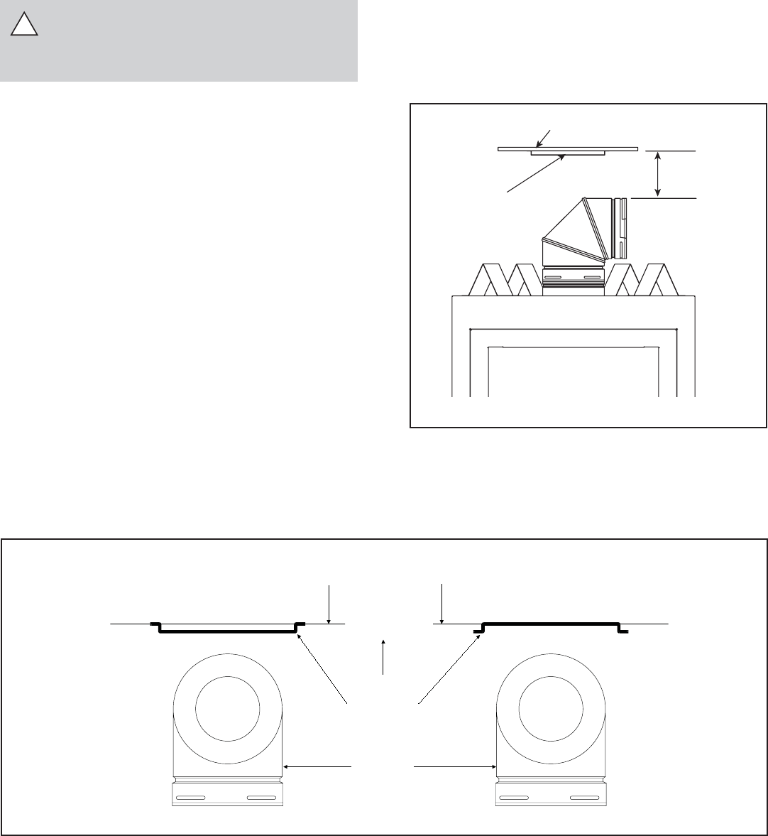
Figure 11
!
DIRECTION
UP
HEAT SHIELD
COMBUSTIBLE SURFACE
90 ELBOW
0
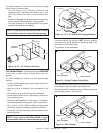
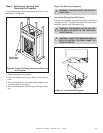
Figure 12
CORRECT INCORRECT
COMBUSTIBLE
SURFACE
HEAT
SHIELD
3“ MIN.
(76 MM)
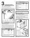
3. Install Support Brackets
Refer to Cinch Pipe and Termination Cap installation in-
structions.
To Install the Heat Shield:
1. Determine if the heat shield is required. Do so by measuring
the vertical distance between the top horizontal surface of
the elbow to any combustible surface above. If the distance
is more than 4 inches, the heat shield is NOT required. If it
is 4 inches or less, the heat shield IS REQUIRED. Install
per the following steps. See Figure 11.
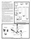
2. Fasten the shield in place using the four pilot holes
provided in the part. The shield should be oriented such
that the 13 1/8 inch dimension (longest dimension) is
running in the same direction the elbow is pointing. The
shield should be centered directly above the elbow, and
positioned so that it creates a 1/2 inch airspace between
the shield and the combustible surface. See Figure 12.
Refer to Cinch Pipe and Termination Cap installation in-
structions.
• Continue adding vent components, locking each suc-
ceeding component into place.
• Ensure that each succeeding vent component is securely
fi tted and locked into the preceding component in the
vent system.
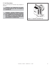
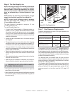
4. Install Firestops
For Horizontal Runs - Firestops are REQUIRED on
both sides of a combustible wall through which the vent
passes.
NOTE: Model DVP-TRAP does not need an exterior
fi restop on an exterior combustible wall.
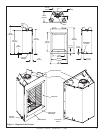
• 90° elbows may be installed and rotated to any point around
the preceding component’s vertical axis. For elbows that
are changing the vent direction, one screw minimum
should be put in the outer vent at the joint to prevent the
elbow from rotating.
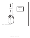
WARNING: INSTALLATION OF THIS FIRE-
PLACE REQUIRES THE USE OF HEAT SHIELD
570-290 ABOVE THE FIRST 90º ELBOW IN THE
VENTING SYSTEM.