


Heat & Glo • Cyclone-Cust • 2061-900 Rev. L • 10/088
Fire Risk.
• Construct chase to all clearance specifi cations
in manual.
• Locate and install appliance to all clearance
specifi cations in manual.
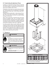
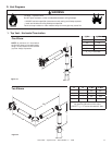
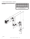
B. Constructing the Appliance Chase
A chase is a vertical boxlike structure built to enclose the
gas appliance and/or its vent system. Vertical vents that
run on the outside of a building may be, but are not re-
quired to be, installed inside a chase.
Construction of the chase may vary with the type of build-
ing. These instructions are not substitutes for the require-
ments of local building codes. Local building codes MUST
be checked.
Chases should be constructed in the manner of all out-
side walls of the home to prevent cold air drafting prob-
lems. The chase should not break the outside building
envelope in any manner.
Walls, ceiling, base plate and cantilever fl oor of the chase
should be insulated. Vapor and air infi ltration barriers
should be installed in the chase as per regional codes for
the rest of the home. Additionally, in regions where cold
air infi ltration may be an issue, the inside surfaces may be
sheetrocked and taped for maximum air tightness.
To further prevent drafts, the wall shield and ceiling
fi restops should be caulked with high temperature caulk
to seal gaps. Gas line holes and other openings should
be caulked with high temp caulk or stuffed with unfaced
insulation. If the appliance is being installed on a cement
slab, a layer of plywood may be placed underneath to
prevent conducting cold up into the room.
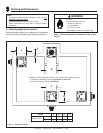
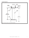
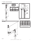
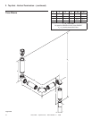
C. Clearances
Figure 3.2 Clearances to Combustibles
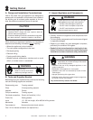
Fire Risk.
Odor Risk.
• Install appliance on hard metal or wood surfaces
extending full width and depth of appliance.
• Do NOT install appliance directly on carpeting,
vinyl, tile or any combustible material other than
wood.
WARNING
WARNING
A
B
C
F
MAX
G
D
E
Clearances to Combustibles
ABCD E F G
Inches 42-1/2 0 0 17-1/2 17-1/2 6-3/8 41-3/8*
mm 1080 0 0 445 445 162 1051
* This dimension must be held to +0 inch to -1/2 inch to assure the fi restop
conceals the connection of the glass tube to the slip section.