


Heat & Glo • Cyclone-Cust • 2061-900 Rev. L • 10/08 13
H
T
V
T
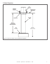
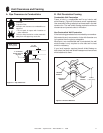
Figure 5.3
Figure 5.4
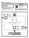
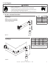
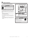
D. Vent Diagrams
1. Top Vent - Horizontal Termination
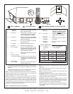
One Elbow
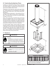
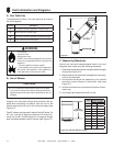
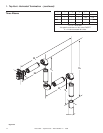
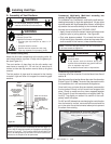
Two Elbows
H
T
H
1
H
2
V
T
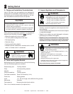
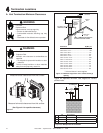
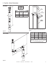
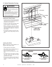
Fire Risk. Explosion Risk.
Do NOT pack insulation or other combustibles between ceiling fi restops.
• ALWAYS maintain specifi ed clearances around venting and fi restop systems.
• Install wall shield and ceiling fi restops as specifi ed.
Failure to keep insulation or other material away from vent pipe may cause fi re.
WARNING
V
T
Min. H
T
Max.
2 ft. 2 ft.
3 ft. 6 ft.
4 ft. 10 ft.
5 ft. 15 ft.
V
T
+ H
T
= 40 ft. Max
NOTE: A minimum of 2 feet before
the fi rst 90º elbow can be achieved by
using a 12 inch section of DVP and the
(cyclone-12slip) slip section.
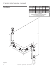
H
1
H
2
V
T
Min. H
T
Max.
* * 2 ft. 2 ft.
* * 3 ft. 6 ft.
* * 4 ft. 10 ft.
* * 5 ft. 15 ft.
V
T
+ H
T
= 40 ft. Max.
*No specifi c restrictions on this value
EXCEPT V
T
+ HT cannot exceed 40 ft. Max.