


Page 9
Cumberland Gap Wood Stove
R
September 1, 2008
7006-188E
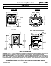
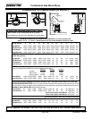
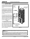
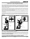
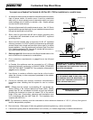
WHEN LOCATING YOUR STOVE consider safety, convenience, traffic flow, and the fact that the stove will need a chimney and chimney
connector. It is a good idea to plan your installation on paper, using exact measurements for clearances and floor protection, before
actually beginning the installation. If you’re not using an existing chimney, place the stove where there will be a clear passage for a
factory-built listed chimney through the ceiling and roof.
AVOID FIRE: Maintain the designated clearances to combustibles. Insulation must not touch the chimney. You must maintain the
designated air space clearance around the chimney. This space around a chimney is necessary to allow natural heat removal from the
area. Insulation in this space will cause a heat buildup, which may ignite wood framing. NOTE: Clearances may only be reduced by
means approved by the regulatory authority having jurisdiction.
WE RECOMMEND that you have a qualified building inspector and your insurance company representative review your plans before
and after installation.
LOCATING YOUR STOVE
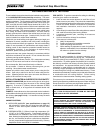
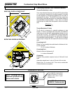
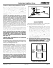
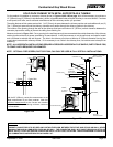
SIDE FUEL-LOADING-DOOR LOCKING MECHANISM
The side fuel-loading-door is shipped locked in place. You must
first decide where you are locating your stove and determine if
you meet the minimum required clearances from combustibles
for loading wood into the firebox from the side door. If you do not
meet the clearances found on pages 6-8, leave the door locked in
place. If you unlock the door without meeting the minimum requried
clearances YOU WILL VOID YOUR WARRANTY AND ASSUME
ALL RESPONSIBILITY. If you do meet the minimum clearances,
follow the steps to unlock the door. If in the future you decide to
relocate your stove, again determine if you meet the mimimum
required clearances to combustibles in the new location. If you
do not, you are required to lock the door shut and it must remain
locked at all times.
1. Open front doors.
2. Using a 5-32 Allen wrench,
remove the bolt from the lock-
ing bracket.
3. Save the bracket and bolt for
potential future use.
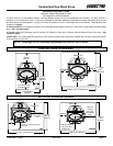
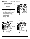
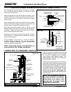
LEG LEVELING SYSTEM
1. Thread Allen bolts through nuts until flush. Figure 9A. The
Allen bolts and nuts are included in the component pack inside the stove
firebox.
2. Slide assembled nuts and bolts into slots on legs with the nuts on the bottom. Figure 9B. Use a 5-32" (4mm) Allen wrench to adjust
legs up and down to desired level. Figure 9C
Fig 9C - Bolt fully extended
Figure 9B
Figure 9A
UNLOCK SIDE FUEL DOOR
IMPORTANT!
If stove is relocated it must meet minimum required clearances in new
location to use the side fuel loading door or door must be locked in place.