


Page 36
250-7251F
September 1, 2008
R
Castile Pellet Insert
11
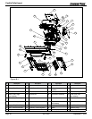
Reference Materials
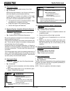
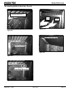
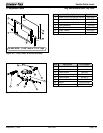
7. Heat Exchangers
The heat exchangers transfer heat from the exhaust system
into convection air. There are 2 clean out rods located under
the heat exchangers.
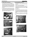
8. Heat Output Switch
The heat output switch is located on the lower right side of
firebox, behind the right face above the reset button. The
function of the heat output switch is to regulate the burn rates;
low, medium and high settings.
9. Igniter
The igniter is mounted on the base of the firepot. Combustion
air travels over the red hot igniter creating super heated air
that ignites the pellets.
10. Junction Box And Wiring Harness
The junction box is located behind right cast side of the
appliance. The junction box and wiring harness are replaced
as one component.
11. Power Supply
The power outlet is located behind the right cast side of the
appliance behind the thermostat block on the junction box.
Check the wall receptacle for 120 volt, 60 Hz (standard
current). Make sure the outlet is grounded and has the correct
polarity. A good surge protector is recommended. When
operating with a generator you need at least 600 watts of
power, or with an inverter at least 800 watts of power available
for the appliance during the start cycle.
12. Red Call Light
The red call light is located behind the fuse behind the right
cast side. The function of the red call light is to indicate that
the thermostat is calling for heat.
13. Reset Button
The reset button is located on the lower right side of firebox
behind right face and below the heat output control switch. The
function of the switch is to momentarily open the thermostat
circuit, which restarts the system.
14. Thermocouple
The thermocouple is located on top of the firepot inside
the thermocouple cover (ceramic protection tube). The
thermocouple sends a millivolt signal to the control box
indicating the preset temperatures of the green and red lights
have been obtained.
15. Thermostat
The appliance is designed to run on a 12 volt AC thermostat.
The heat anticipator, if present, should be set on the lowest
setting available.
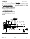
When describing the location of a component
part it is always AS YOU FACE THE FRONT
OF THE APPLIANCE.
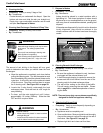
2. Convection Blower
The convection blower is mounted at the bottom rear of the
appliance. There are 2 impellers, one on each side of the
motor. The convection blower pushes heated air through the
heat exchange system into the room.
3. Exhaust Blower
The exhaust blower is mounted on the right side of the
appliance behind the right cast side. The exhaust blower is
designed to pull the exhaust from the appliance and push it
out through the venting system.
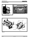
4. Feed System
The feed system is located on the right side and can be
removed as an entire assembly. The assembly includes
the feed motor, mounting bracket, bearing and feed spring
(auger). The hollow feed spring (auger) pulls pellets up the
feed tube from the hopper area and drops them down the
feed chute into the firepot.
5. Firepot
The firepot is made of high quality ductile iron and has a
cleaning pull-out rod. The floor of the firepot opens for
cleaning when you pull out the rod. Be sure that the floor
returns to a completely closed position or your appliance will
not operate properly.
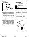
6. Fuse
The fuse is located on the right side behind the control box.
The fuse will blow should a short occur and shut off power
to the appliance.
NOTE:
Do NOT open the control box. This will void the
warranty. If you need to plug in or remove the control
box you must first unplug the appliance.
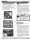
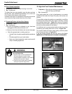
1. Control Box
a. The control box is located on lower right side of
appliance, behind cast side on top of the junction
box.
b. There is a light located inside of the control box. The
internal light will turn green when the appliance has
reached a temperature of 200
ο
F (93
°
C) in the firepot.
and will turn red when it reaches 600
o
F (315
°
C).
c. There is also an internal blue light located in the upper
left corner of the control box. When you plug in the
appliance the blue light will automatically start blinking
6 blinks every 10 seconds for 60 seconds and then will
stop.
A. Component Function