


Page 16
250-7251F
September 1, 2008
R
Castile Pellet Insert
7
Appliance Set-Up
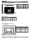
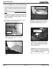
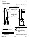
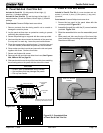
B. Leveling System
Figure 16.4
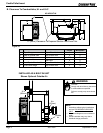
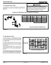
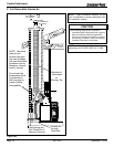
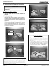
A. Reversible Top or Rear Flue Adapter
The back legs are adjustable to allow for customized fit
into zero clearance boxes.
1. Loosen 2 top screws and remove 2 bottom screws.
2. Adjust leg to desired height. Leg can slide up (shorter)
or down (longer) to level the insert.
3. Tighten 2 top screws.
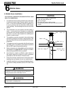
4. Drill 2 holes for the bottom 2 screws and re-install
screws. Figure 16.5.
Loosen top 2 screws and remove
bottom 2. Adjust leg to desired height.
Drill 2 holes and
re-install bottom 2
screws
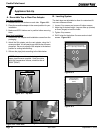
Ammo Can Latches
Top Vent Installation
1. Release ammo can latches on each side. Figure 16.1.
2. Place the reversible adapter in the correct position for your
installation.
3. Make sure BOTH latches are in position before securing
them.
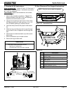
Rear Vent Installation
1. Remove the 90
o
adapter and installation screws from the
packaging.
2.
Attach the 90
o
adapter onto the vent adapter, using the 3
screws provided. You will need to pre-drill the holes for screw
placement. Be sure to adjust the 90
o
adapter to the desired
position for venting before drilling.
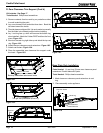
3. Silicone the pipe joints according to the Note below.
screw
Figure 16.5
Figure 16.1 - Top Vent
Figure 16.2 - Rear Vent
Figure 16.3 - Rear Vent
NOTE: All pipe must be sealed using welded
seam pipe whenever possible. Seal pipe joints
with high temperature silicone, minimum rate of
500
0
F (260
0
C).