


Page 18
250-7251F
September 1, 2008
R
Castile Pellet Insert
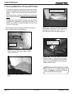
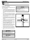
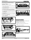
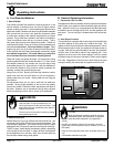
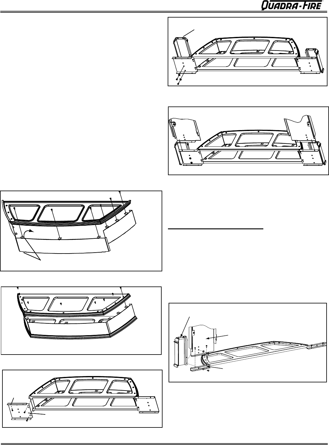
Install Sides
First
Install Front Last
Bend top and bottom tabs toward inside
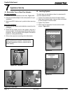
OT
-
Turn right side up and attach top cast rin g
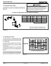
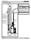
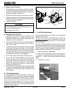
Zero Clearance Panel Extension
Alignment
Hole
T
L
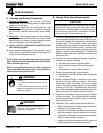
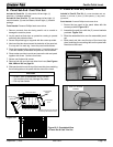
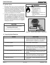
Base Plate Only Installation
Kit Includes: See Page 17
Tools Needed: Phillips head screwdriver
Parts Needed: (1) cast ring (2) base zero clearance panel
extensions. Discard balance of parts.
Tools Needed: Phillips head screwdriver
1. Attach base zero clearance panel extensions to cast
ring.
2. Place assembly under appliance.
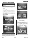
1.
Remove contents from box and lay on protective surface
to avoid scratching the paint.
2. Lay zero clearance front and sides face down. Bend the
tab down toward the inside.
3.
The side pieces are shipped flat. It
is much easier to manually
flex the sides into a bowed position before installing.
4.
Lay 1 cast ring face up, which
will become the bottom ring
when installed. Attach the 2 sides FIRST and then the front
piece. Figure 18.1.
5. Now turn the cast ring right side up
and attach the top cast
ring . Figure 18.2.
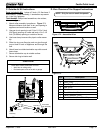
6. Attach the zero clearance panel extensions. Figure 18.3
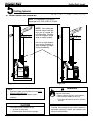
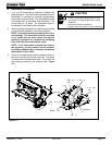
7. Attach cast footers. Figure 18.4.
8. Place the assembled zero clearance trim support under
the insert. Figure 18.5.
Zero Clearance
Panel Extension
Panel Leg
Cast Trim Footer
D. Zero Clearance Trim Support (Cont’d)
Figure 18.1
Figure 18.2
Figure 18.3
Figure 18.4
Figure 18.5
Figure 18.6