


20
Heat & Glo • 6000TRSI-AUC • 2078-900 Rev. G • 12/06
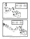
FIGURE 1.30
NOTE: IF ANY OF THE ORIGINAL
WIRE AS SUPPLIED WITH THE
APPLIANCE MUST BE RE-
PLACED, IT MUST BE REPLACED
WITH TYPE 105
•
C RATED WIRE.
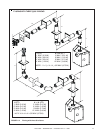
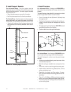
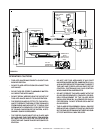
FIGURE 1.31
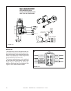
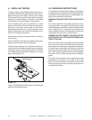
Blower Fan
This heater has a factory installed blower fan,
electrical junction boxes, variable speed rheo-
stat control switch and temperature sensor
switch for the blower fan. These components
are located behind the lower door.
The factory installed power cord is attached
on the lower front right exterior side of the
heater. Figure 1.30 shows the blower fan,
switches, and blower fan wiring diagram. See
Figure 1.31 for wire connection detail.
BROWN
BROWN
BLUE
BLACK
BLUE
BLACK
(HOT) BROWN
(NEUTRAL) BLUE
BLACK
BLACK
BLUE
BROWN
GREEN/YELLOW
BLOWER
TEMPERATURE
SENSOR SWITCH
240VAC JUNCTION BOX
VARIABLE
SPEED
CONTROL
BROWN
BLUE
BLACK
BROWN
BLUE
BROWN
BLUE
BLACK
GREEN/YELLOW
STRIPE
GREEN/YELLOW STRIPE