


18
Heat & Glo • 6000TRSI-AUC • 2078-900 Rev. G • 12/06
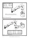
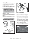
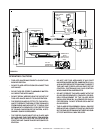
FIGURE 1.28
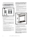
D. CONNECTING THE GAS SUPPLY
The gas is introduced to the appliance on the left hand
side. See Figure 1.28.
After the gas pipe installation is complete, check care-
fully all gas connections for leaks with a commercially-
available, noncorrosive leak check solution. Be sure to
rinse off all leak check solution following testing. DO
NOT USE AN OPEN FLAME.
NOTE: THE GAS SUPPLY LINE SHOULD BE
PURGED OF ANY TRAPPED AIR PRIOR TO THE
FIRST FIRING OF THE UNIT.
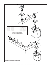
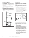
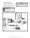
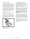
FIGURE 1.27 Termination Cap
For Vertical Terminations - To locate the flue and install
the flue sections:
• Locate and mark the flue center point on the under-
side of the roof, and drive a nail through the center
point.
• Make the outline of the roof hole around the center
point nail.
• The size of the roof hole framing dimensions depend
on the pitch of the roof. There MUST BE a 1-inch (25
mm) clearance from the vertical flue pipe to combus-
tible materials.
• Mark the roof hole accordingly.
• Cover the opening of the installed flue pipes.
• Cut and frame the roof hole.
• Use framing lumber the same size as the roof rafters
and install the frame securely. Flashing anchored to
the frame must withstand heavy winds.
• Continue to install concentric flue sections up through
the roof hole and up past the roof line until you reach
the appropriate distance above the roof.
1” (25mm)
7-1/2”
(192mm)
MINIMUM
!
• Adjust the termination cap to its final exterior posi-
tion on the building and interlock the flue sections.
WARNING: THE TERMINATION CAP
MUST BE POSITIONED SO THAT THE
ARROW IS POINTING UP.
• Use a high-temperature sealant gasket to seal be-
tween the pipe and exterior firestop.
CAUTION: FOLLOW THE REQUIREMENTS OF THE
AGA GAS INSTALLATION CODE FOR MINIMUM
HEIGHT REQUIREMENTS ABOVE THE ROOF.
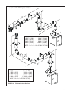
To seal the roof hole, and to divert rain and snow from
the flue system:
• Attach a flashing to the roof using nails, and use a
non-hardening mastic around the edges of the flash-
ing base where it meets the roof.
• Attach a storm collar over the flashing joint to form
a water-tight seal. Place non-hardening mastic
around the joint, between the storm collar and the
vertical pipe.
• Slide the termination cap over the end of the flue
pipe and rotate the pipe clockwise 1/4 turn.
GAS LINE
ACCESS