


17
Heat & Glo • 6000TRSI-AUC • 2078-900 Rev. G • 12/06
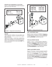
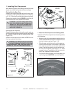
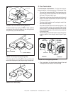
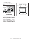
FIGURE 1.23 Hole and New Framing Members
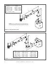
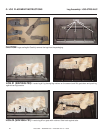
If the area above the ceiling is NOT an attic, position
and secure the ceiling firestop on the ceiling side of
the previously cut and framed hole.
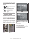
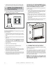
FIGURE 1.24 Ceiling Firestop (Ceiling Side)
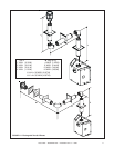
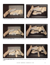
If the area above the ceiling IS an attic, position and
secure the firestop on top of the previously framed hole.
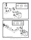
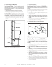
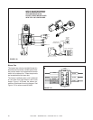
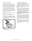
For Horizontal Terminations - To attach and secure
the termination to the last section of horizontal flue:
• The rear flue heat shield MUST be placed one inch
above the top of the flue between the wall shield and
the base of the termination cap.
• One section of the heat shield is attached to the wall
shield. The other is attached to the termination cap
in the same manner.
• The heat shield sections will overlap to match the
wall thickness (depth).
• If the wall thickness does not allow the required 1-1/2
inch heat shield overlap, an extended heat shield
must be used. The extended heat shield will need to
be cut to the thickness of the wall and be attached
to the wall shield.
• The small leg in the shield rests on top of the flue to
properly space it from the pipe section (see Figure
1.26).
JOIST
CEILING FIRESTOP
CEILING
NAILS (4 REQUIRED)
CEILING
CEILING FIRESTOP
RAFTER
NAILS (4 REQUIRED)
CEILING
NEW
FRAMING
MEMBERS
EXISTING CEILING
JOISTS
CHIMNEY
HOLE
10" (254mm)
10” (254mm)
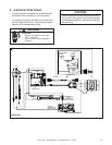
FIGURE 1.26 Flueing through the Wall
EXTERIOR
INTERIOR
Interior
Wall Shield
Inner Flue
Rear Vent
Heat Shield
38mm min.
overlap
Outer Flue
38mm min.
Overlap
FIGURE 1.25 Attic Firestop
• The termination kit should pass through the wall
firestops from the exterior of the building.
C. Flue Termination