


32
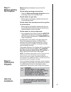
WARNING: DO NOT CONNECT 230 VAC
TO THE WALL SWITCH OR THE
CONTROL VALVE WILL BE DESTROYED.
CAUTION
LABEL ALL WIRES PRIOR TO DISCONNECTION
WHEN SERVICING CONTROLS. WIRING ER-
RORS CAN CAUSE IMPROPER AND DANGER-
OUS OPERATION. VERIFY PROPER OPERA-
TION AFTER SERVICING.
!
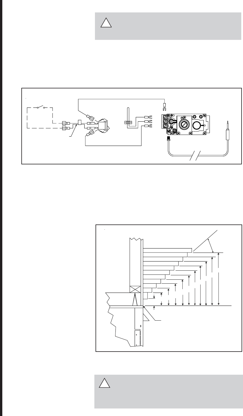
OPTIONAL WALL SWITCH
THERMOSTAT OR REMOTE
REMOTE SWITCH
PIGTAIL
OFF
ON
ON/OFF
SWITCH
THERMOPILE
TP/TH
TP
TH
GAS VALVE
THERMOCOUPLE
!
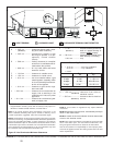
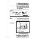
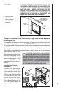
Step 9
Finishing
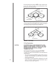
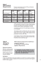
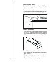
The following diagram shows the minimum vertical
and corresponding maximum horizontal dimensions
of fireplace mantels or other combustible projections
above the top front edge of the fireplace. See Figures
2 , 3 and 4 for other fireplace clearances.
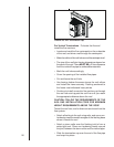
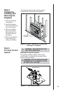
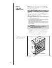
Only non-combustible
materials may be used
to cover the black
fireplace front.
Figure 29. Standing Pilot Ignition Wiring Diagram
WARNING: WHEN FINISHING THE
FIREPLACE, NEVER OBSTRUCT OR
MODIFY THE AIR INLET/OUTLET
GRILLES IN ANY MANNER.
5
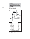
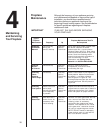
TOP FRONT EDGE
OF FIREPLACE
NOTE: ALL DIMENSIONS SHOWN
IN CENTIMETERS
7.6
10.2
12.7
15.2
15.8
20.3
22.7
25.4
27.9
30.5
45
o
Figure 30. Minimum Vertical and Maximum
Horizontal Dimensions of Combustibles
above Fireplace