


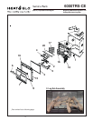
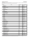

12
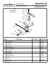
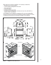
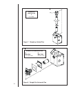
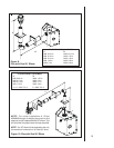
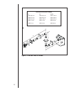
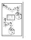
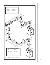
Figure 5. Flue Components and Terminations
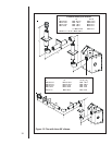
A. Flue System Approvals
These models have flue starting collars on both the
top and the back of the unit. Depending upon the
installation, decide which ONE set of starting collars
will be used to attached the flue system. The starting
collar sealing cap must remain on the starting collar
NOT used.
These models use DVP-series direct flue components
when using the TOP and REAR flue collars.
Approved flue system components are labeled for
identification. NO OTHER FLUEING SYSTEMS OR
COMPONENTS MAY BE USED. Detailed installation
instructions are included with each flue termination kit
and should be used in conjunction with this Installers
Guide. Figure 4 shows flue system components and
terminations.
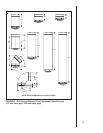
Identifying Flue Components
The flue systems installed on this gas fireplace may
include one, two, or three 90°
elbow assemblies. The
relationships of vertical rise to horizontal run in flue
configurations using 90° elbows MUST BE strictly
adhered to. The rise to run relationships are shown in the
flueing drawings and tables on the next several pages.
NOTE: Two 45° elbows may be used in place of one
90° elbow. You MUST always maintain the MAXIMUM
and MINIMUM rise-to-run ratios in the flue system
when using 45° elbows.
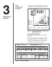
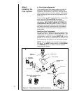
Step 3
Installing the
Flue System
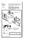
Flue system termination kits
HORIZONTAL
TERMINATION
WALL FIRESTOP
90 DEGREE
ELBOW
VERTICAL
TERMINATION
STORM COLLAR
ROOF FLASHING
HORIZONTAL PIPE
SUPPORT
PIPE LENGTH
WALL BRACKETCEILING
FIRESTOP
DVP-SERIES
DVP-TRAP
DVP-TVHW
SERIES