


28
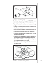
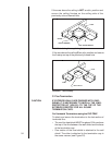
V
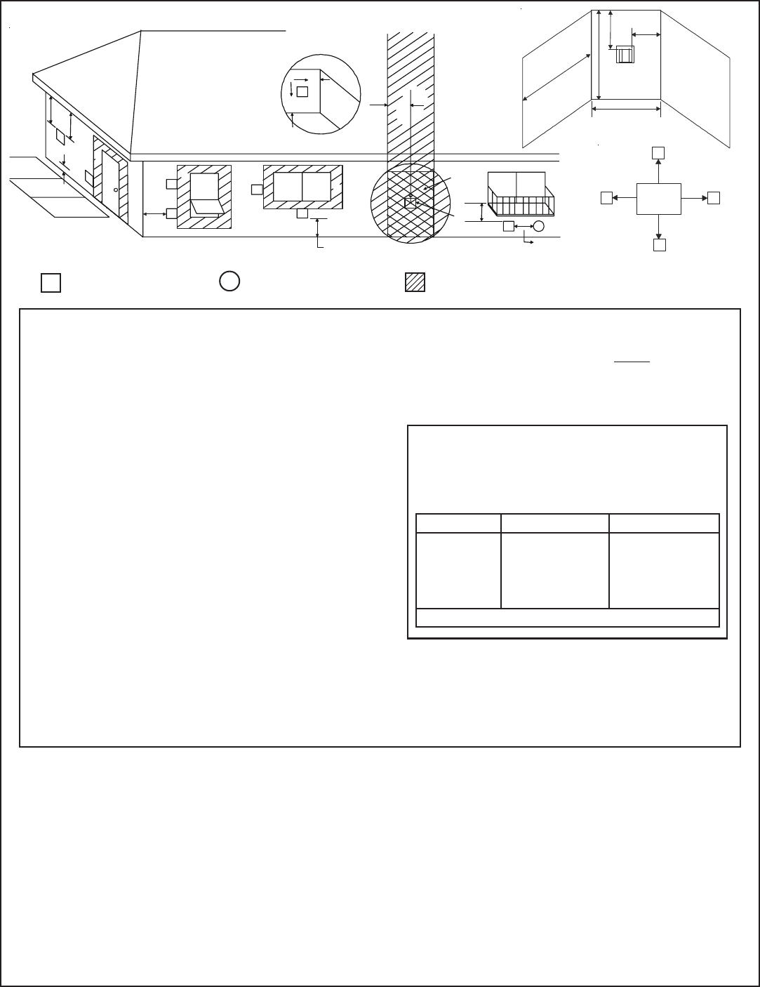
= VENT TERMINAL
X
= AIR SUPPLY INLET
= AREA WHERE TERMINAL IS NOT PERMITTED
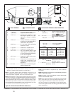
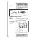
Figure 25 Vent Termination Minimum Clearances
L = 2.1 M ...................... clearance above paved side-
walk or a paved driveway lo-
cated on public property
M* = 50.8 cm ................. clearance under veranda, porch,
deck, balcony or overhang
118.9 cm ............... vinyl
CAUTION: IF EXTERIOR WALLS ARE FINISHED WITH VINYL SIDING, IT IS SUGGESTED THAT A VINYL PROTECTOR KIT BE INSTALLED.
* only permitted if veranda, porch, deck or balcony is fully open on a
minimum of 2 sides beneath the floor, or meets Note 2.
NOTE 1: On private property where termination is less than 2.1 M
above a sidewalk, driveway, deck, porch, veranda or balcony, use of
a listed cap shield is suggested. (See vents components page)
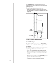
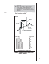
NOTE 2: Termination in an alcove space (spaces open only on one side
and with an overhang) are permitted with the dimensions specified for
vinyl or non-vinyl siding and soffits. 1. There must be 91.4 cm minimum
between termination caps. 2. All mechanical air intakes within 3.0 M of
a termination cap must be a minimum of 91.4 cm below the termination
cap. 3. All gravity air intakes within 91.4 cm of a termination cap must
be a minimum of 30.5 cm below the termination cap.
M
N
P
R
Q
(See Note 2)
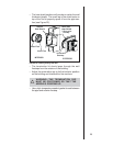
Electrical
Service
V
S
V
S
V
T
D
V
NOTE 3: Local codes or regulations may require different
clearances.
NOTE 4: Termination caps may be hot. Consider their proximity to
doors or other traffic areas.
NOTE 5: Location of the vent termination must not interfere with
access to the electrical service.
NOTE: Vent system termination is permitted in porch areas with
two or more sides open. You must follow all side walls, over-
hang and ground clearances as stated in the instructions.
Heat & Glo assumes no responsibility for the improper perfor-
mance of the appliance when the venting system does not meet
these requirements.
D
E
B
L
v
v
v
v
v
v
v
v
B
B
A
H
M
X
J or K
I
A
G
F
91.4 cm
B
______________________________________________________________________
______________________________________________________________________
______________________________________________________________________
______________________________________________________________________
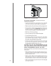
Q
MIN
R
MAX
1 cap 91.4 cm 2 x Q
ACTUAL
2 caps 1.8 M 1 x Q
ACTUAL
3 caps 2.7 M 2/3 x Q
ACTUAL
4 caps 3.7 M 1/2 x Q
ACTUAL
Q
MIN
= # termination caps x 3 R
MAX
= (2 / # termination caps) x Q
ACTUAL
N = 15.3 cm ................. non-vinyl sidewalls
30.5 cm ................. vinyl sidewalls
P = 2.4 M
Alcove Applications
S = 15.3 cm .................. clearance from sides of
electrical service
T = 30.5 cm................... clearance above electrical
service
(See Note 5)
(See Note 5)
A = 30.5 cm ............... clearances above grade, veran-
da, porch, deck or balcony
B = 30.5 cm ............... clearances to window or door
that may be opened, or to per-
manently closed window.
(Glass)
D = 50.8 cm ............... vertical clearance to unventilat-
ed soffit or to ventilated soffit lo-
cated above the terminal
= 84.8 cm ............... for vinyl clad soffits and below
electrical service
F = 22.9 cm .............. clearance to outside corner
G = 15.3 cm ............... clearance to inside corner
H = 91.4 cm ............... not to be installed above a gas
meter/regulator assembly within
91.4 cm horizontally from the cen-
ter-line of the regulator
I = 91.4 cm ............... clearance to gas service regu-
lator vent outlet
J = 22.9 cm ................. clearance to non-mechanical air
supply inlet to building or the
combustion air inlet to any other
appliance
K = 91.4 cm ................. clearance to a mechanical (pow-
ered) air supply inlet
(See Note 1)
(See Note 1)