


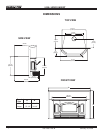

5100-I WOOD INSERT
Page 12
January 30, 2004
R
250-1960 Rev B
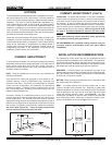
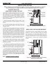
INSTALLATION IN CANADA
MASONRY and HEAT-CIRCULATING
(INSTALLATIONS INTO FACTORY-BUILT FIREPLACES ARE PROHIBITED IN CANADA)
Whether installed in a masonry or heat-circulating replace, this replace insert must be installed with a continuous chim-
ney liner of 6” (152mm) diameter extending from the replace insert to the top of the chimney. The chimney liner must
conform to the Class 3 requirements of CAN/ULC-S635, Standard for Lining Systems for Existing Masonry or Factory-Built
Chimneys and Vents, or CAN/ULC-S640, Standard for Lining Systems for New Masonry Chimneys.
• Do not remove bricks or mortar from replace to accommodate insert.
• The face of the replace must be sealed to prevent room air passage into the chimney cavity.
• The permanent metal warning label provided must be afxed to the back of the replace with screws or nails
to the replace, in a location readily visible should the replace insert by removed, stating that the replace may
have been altered to accommodate the insert, and must be returned to original condition for use as a conventional
replace.
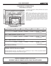
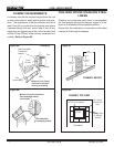
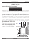
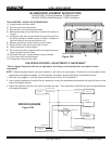
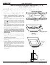
USE OF LEVELING BOLTS
Figure 12A
Two leveling bolts, 3/8” x 4” are shipped inside the component pack found inside the rebox.
NOTE: Not all installations will require the use of the leveling bolts. If the leveling bolts are necessary, you will also need
sheetmetal guides placed under the leveling bolts to slide insert into position.
1. Remove the bolts from the component pack.
2. Locate the weld nuts welded to each side of the insert bottom and insert the bolts.
3. Position insert on hearth with rear of insert extending into replace opening.
4. Extend leveling bolts downward to level insert.
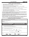
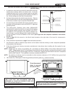
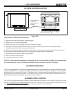
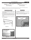
SECURING LINER TO CHIMNEY RING
There are two options to secure the liner to the chim-
ney ring: (See Figure 12A).
Option One: If there is enough room on the top of the
insert to work, hand bend the two tabs upward 90°.
Secure the liner with the supplied hex head bolts 1/4-
20-3/4.
Option Two: Remove the manifold tubes, berboard
bafe and ceramic blanket. From inside the rebox,
pull liner down through the chimney ring below the
outer skin. There are two pre-drilled holes in the chim-
ney ring 180° apart. Secure the liner with the supplied
hex head bolts 1/4-20-3/4.
NOTE: Tabs are shipped from factory in a at position.
Bend upwards 90 degrees.
A
t
t
a
c
h
l
i
n
e
r
w
i
t
h
2
t
a
b
s
2 pre-drilled holes on
chimney ring under outer skin
(access through firebox)