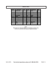
SKU 92274 For technical questions, please call 1-800-444-3353. PAGE 9
ASSEMBLY AND OPERATING INSTRUCTIONS
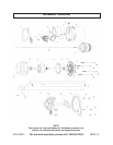
NOTE: For additional information regarding the parts listed in the following pages, refer
to the Assembly Diagram on page 14.
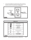
1.
If necessary,
have a certified electrician install (within six feet of where the Sump
Pump will be located) a 115 volt, grounded, electrical outlet that is dedicated only
to the Pump. Any outlet must be above the water line.
1. WARNING! Always make sure the Sump Pump is unplugged from its
electrical outlet
prior
to assembling the unit, unclogging the unit, or making any
adjustments to the unit.
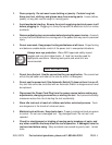
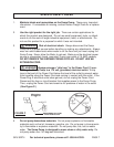
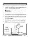
2. Snap the Hook (20) midway onto the Support (21). (See Figure D.)
3. Insert the threaded end of the Float Rod (10) downward through the eyelet in the
Hook (20). Then, screw on the Float (11). (See Figure D.)
4. Remove the Upper Rubber Stop on the automatic Switch Arm (3) and insert the
top portion of the Float Rod (10) through the hole in the arm of the automatic
Switch (3). Then, replace the Upper Rubber Stop at least 1/2” from the end of
the Float Rod. (See Figure D.)
5. Set the Sump Pump in place, making sure the arm of the automatic Switch (3)
has adequate clearance and will not hang up on the pit wall. (See Figure D.)
6. NOTE: The size of the discharge outlet on the Impeller Case (22) is 1-1/4”
diameter. Only a 1-1/4” diameter Discharge Pipe (not included) must be used.
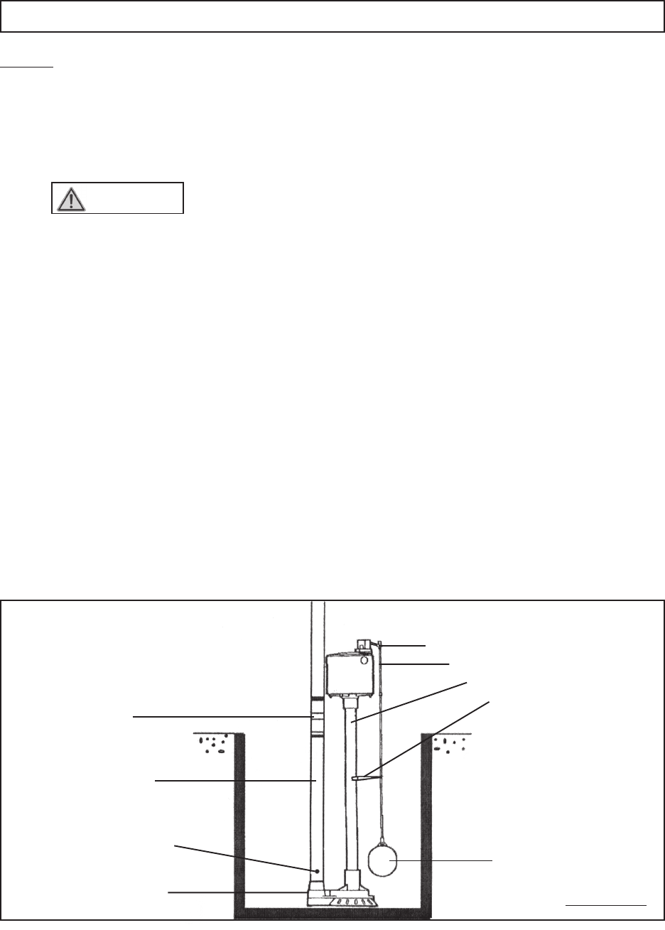
FIGURE D
AUTOMATIC
SWITCH (3)
ARM
FLOAT ROD (10)
HOOK (20)
SUPPORT (21)
FLOAT (11)
IMPELLER CASE (22)
1-1/4” DIAMETER
DISCHARGE PIPE
(NOT INCLUDED)
CHECK VALVE
OR UNION
(NOT INCLUDED)
1/8” AIR BLEED HOLE.
(WATER SPRAY IS NORMAL)