


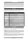
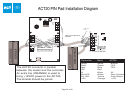
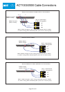
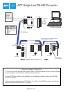

DB25 Male
(Rear View)
7
3 2
Max cable length is 5m using standard alarm cable
or 30m using twin twisted-pair (use 0V in each pair)
Direct Connection from Modem to Controller
Connections for 25 Way male Connector
RX = Pin 3
TX = Pin 2
0V = Pin 7
1. Connect Modem Cable directly
to ACT1000/2000 and Modem
2. In Communications Menu Set:
Address = 1
Direct Conn = Y
3. Controller is now ready to receive calls
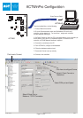
1. Connect the ACT modem to the PC and install modem driver.
2. In ACTWinPro, Click on the Locations and Connections icon on the toolbar.
3. Configure the remote site name in the Location Name.
4. Select the Type of Connection as Modem.
5. Enter the remote sites' telephone number.
6. Select the newly installed modem as the Dialup Modem.
7. Set up remote controller(s) in the Controller View. Set the location as the remote site name.
6. The controller(s) will appear under the remote site name in the System View window.
7. Double click on the telephone icon beside the remote site name in System View window.
8. Modem will now contact remote Site and connect to the controller(s).
9. To finish the call, click the disconnect button on ACTWinPro
ACTWinPro Setup for Modem Operation
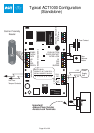
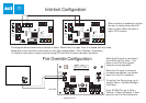
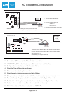
ACT Nework Interface Card
Line 1
Line 2
Line 3
Line 4
SCN C DI DO
+BAT-
C 1 2
C 1 2
C 1 2
C 1 2
~AC~
RS485
RS485
232 Interface
Converter
LED2
LED3
RS232
PORT
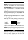
Connections for 25 Way male Connector
Modem Connection for ACT Network
DO = Pin 2
DI = Pin 3
C = NC
SCN = Pin 7
DB25 Male
(Rear View)
7
3 2
1. Connect Network Modem Cable to ACT Network card and Modem
2. In ACT1000/2000 Communications Menu set the controller Address
and set Direct Conn = N
3. Controller(s) now ready to receive calls
ACT Modem Configuration
Page 30 of 32
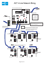
A B
0V
TX
RX
NETWORK
DOORS
A
B
0V
SERIAL/PRINTER
0V
DTR
ACT 2000