


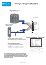
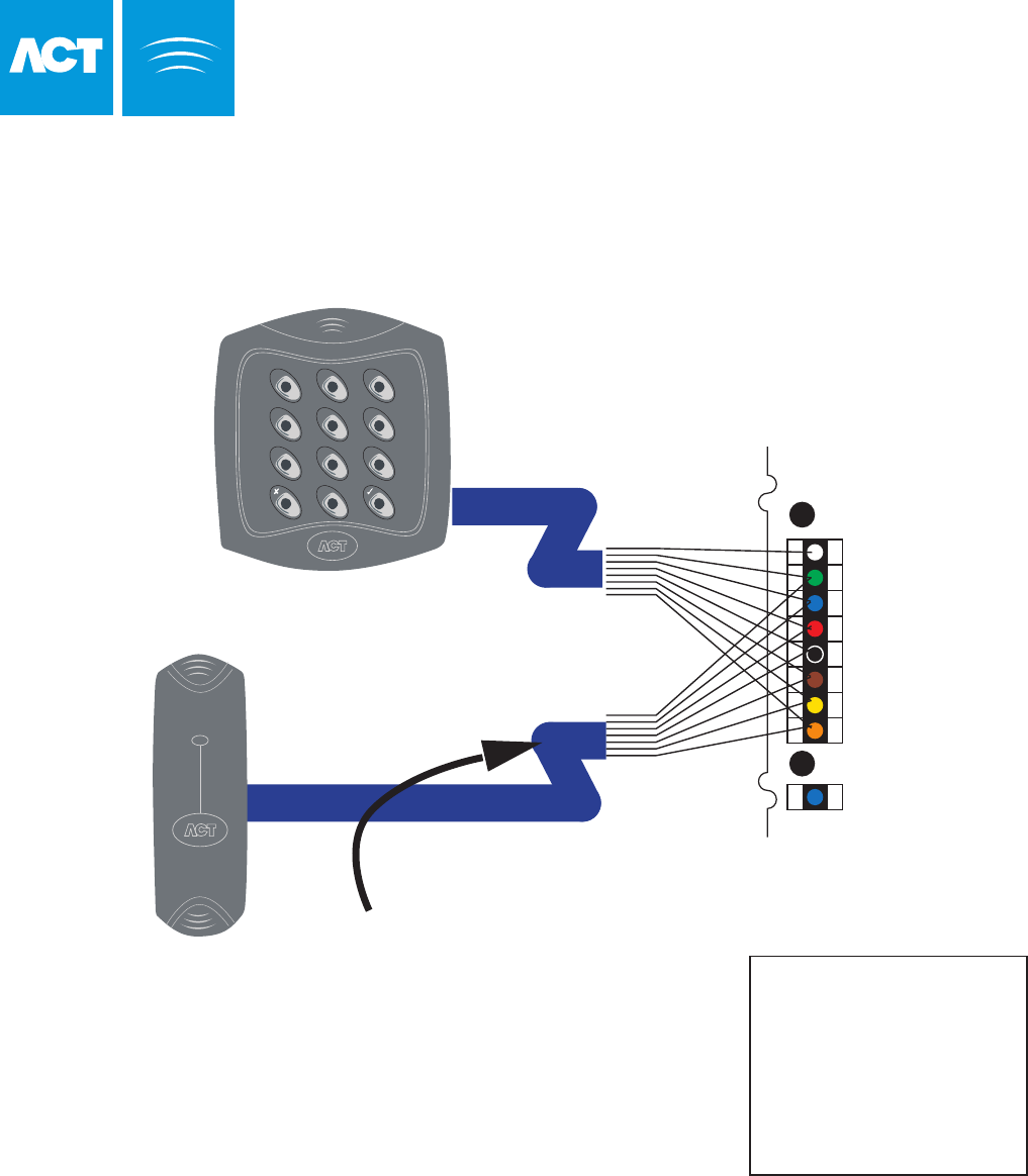
Card / Proximity or Pin
Reader (Entry)
Card or Proximity
Reader (Exit)
Controller
SENSE
CLOCK
DATA
+5V
0V
RED
GREEN
Card/Prox Reader
2 31
5 64
8 97
0
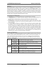
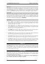
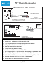
For Wiegand Exit readers
Connect DATA 0 of the exit reader
to SENSE on the controller. Leave
SENSE on the readers unconnected.
Wire both readers in parallel but leave
the SENSE line on the Exit reader unconnected.
The above diagram is valid only
for clock-and-data type readers.
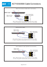
White
Green
Blue
Red
Black
Brown
Yellow
Orange
SENSE
CLOCK (DATA 1)
DATA (DATA 0)
+5v
0v
RD
GREEN
(Buzzer Control)
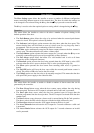
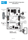
Wiring for Clock and Data / Wiegand Reader
The standard wiring colours for
ACTPro Proximity and Pin readers
is shown above. Readers
may be a maximum of 30m
from the controller when powered
from +5V and a maximum of 100m
when powered from +12V.
The +5V reader supply on ACT controllers is normally rated
at 100mA. Typically this is sufficient to power 2 ACT readers.
Note however that readers from other manufacturers may need
to be powered separately if their current requirements exceed
this or if they require 12V.
Page 23 of 32
Wiring for Entry/Exit Readers