


1A 250VAC
1A 30VDC
0 1 2 3 4 5 6 7 8 9
BATCH:
PRODUCT:
SERIAL NUMBER:
98XX-1
ACT2000 REV2.1
00XXXX
0V
DOOR
CONTACT
PUSH
BUTTON
AUX
INPUT
RELAY 1
N/C N/O
C
OP2
OP3
SENSE
CLOCK
DATA
RED
GREEN
ENTRY/EXIT READER 1
A B
0V
TX
RX
NETWORK
5A 250VAC
5A 30VDC
1A 250VAC
1A 30VDC
5A 250VAC
5A 30VDC
+
CR2032
DOORS
A
B
0V
SERIAL/PRINTER
0V
DTR
+5V
0V
SENSE
CLOCK
DATA
RED
GREEN
ENTRY/EXIT READER 2
+5V
0V
OUTPUTS 1 INPUTS
0V
DOOR
CONTACT
PUSH
BUTTON
AUX
INPUT
OP2
OP3
OUTPUTS 2 INPUTS
TAMPER
MAINS
PRESENT
+12V DC
AUX RLY 1
N/C N/O
C
RELAY 2
N/C N/O
C
AUX RLY 2
N/C N/O
C
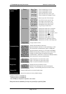
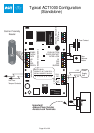
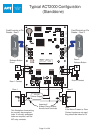
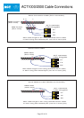
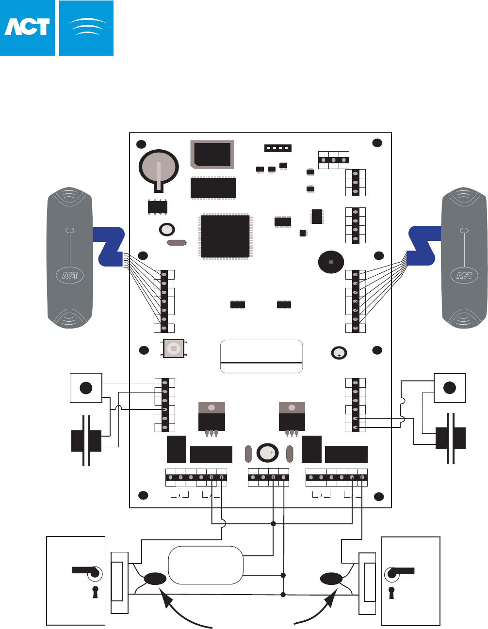
This illustration shows wiring
for normally de-energised
locks. If normally energised
locks are required, use the
N/C relay contacts.
Note:
If the Mains Present or Door
Contact inputs are not used,
they should be linked to 0V
Door 2
Release Button
Door 2 Contact
Release Button
Door 1
Door 1 Contact
Card/Proximity or Pin
Reader - Door 2
Card/Proximity or Pin
Reader - Door 1
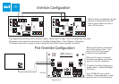
Important!
Always Place Varistor
Across Lock Terminals
Door 2
Door 1
12V DC
Power Supply
12V
0V
- DC
Page 21 of 32
Typical ACT2000 Configuration
(Standalone)