-22-
G0637/G0638 Cyclone Dust Collector
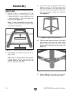
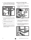
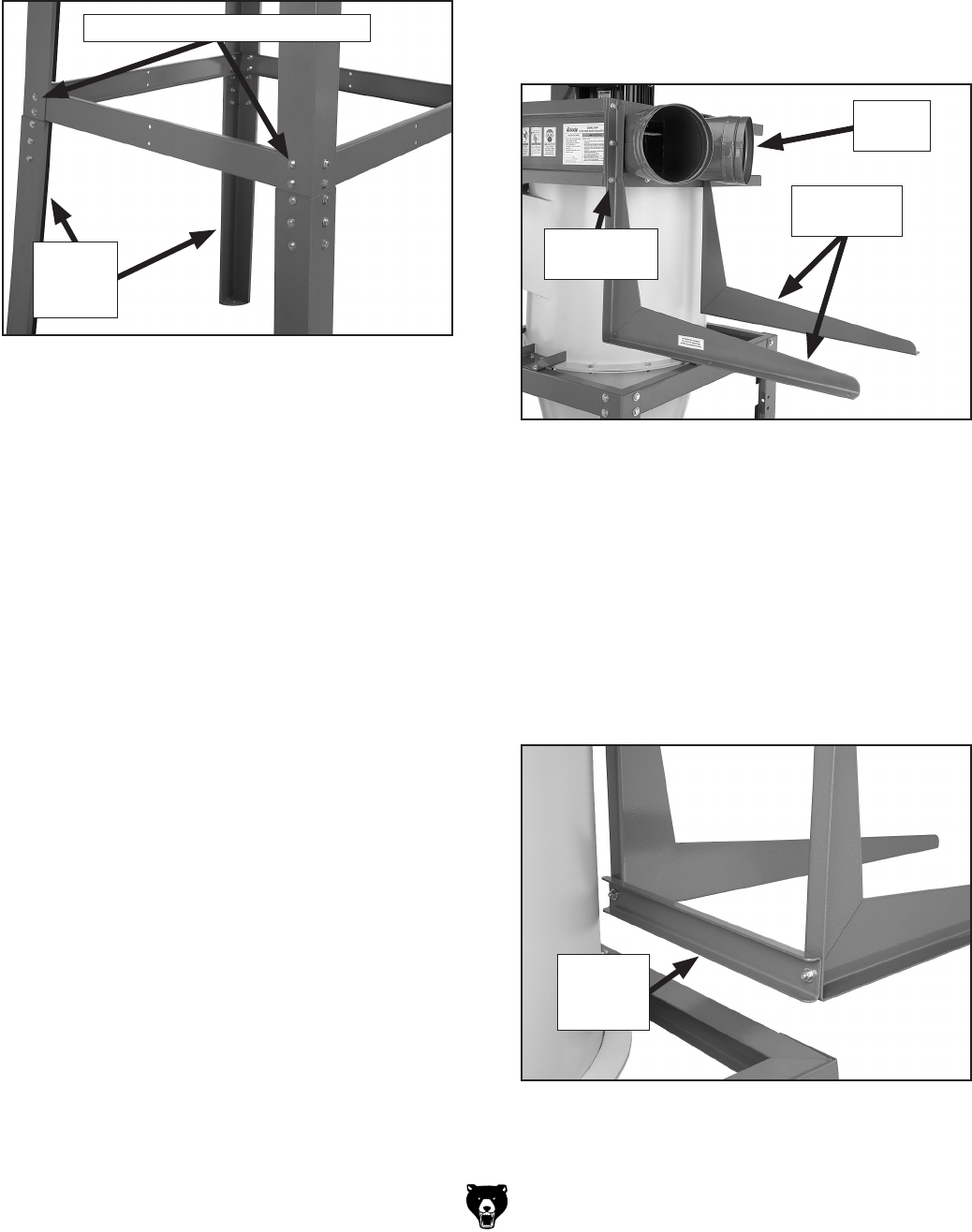
6. To allow the mounting holes of the lower
stand legs to align properly, slightly loosen
the 16 fasteners that connect the lower stand
braces to the upper stand legs
(see Figure
24).
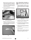
7. Secure the lower stand legs to the upper
stand assembly with (24)
3
⁄8"-16 x
3
⁄4" hex
bolts, (48)
3
⁄8" flat washers, and (24)
3
⁄8"-16
lock nuts.
8. Re-tighten the 16 fasteners connecting the
lower stand braces to the assembly
.
9. Remove the power lifting equipment from the
assembly.
Note: The only other use for the power lift-
ing equipment is moving the dust collection
system into its permanent position when the
assembly is complete.
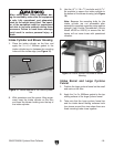
Outlet Port and Canister Filters
1. Apply the 3 x 6 x 1100mm gasket to the
square side of the outlet port.
2. Mount the outlet port to the blower hous-
ing with (4)
5
⁄16"-18 x 1" hex bolts, (8)
5
⁄16"
flat washers, and (4)
5
⁄16"-18 hex nuts (see
Figure 25).
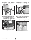
3. Attach the filter L-braces to either side of the
outlet port on the blower housing with (6)
5
⁄16"-
18 x 1" hex bolts, (12)
5
⁄16" flat washers, and
(6)
5
⁄16"-18 hex nuts.
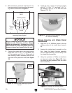
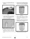
4. Secure the short filter brace support to the
back of the filter L-braces with (2)
3
⁄8"-16 x
3
⁄4"
hex bolts, (4)
3
⁄8" flat washers, and (2)
3
⁄8"-16
hex nuts
(see Figure 26).
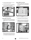
Figure 26. Short filter brace support attached.
Short
Brace
Support
Figure 24. Lower stand legs attached to the
upper stand assembly.
Lower
Stand
Legs
Lower Stand Brace Fasteners
Figure 25. Filter L-braces mounted to blower
housing.
Filter
L-Braces
Mounting
Hex Bolts
Outlet
Port


