


Instructions
3A1495C 9
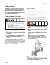
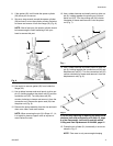
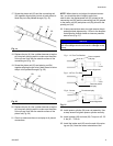
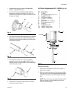
17. Screw the piston rod (23) and the connecting rod
(32) together aligning the pin hole in both pieces to
allow the pin to be pushed through (Fig. 19).
18. Replace the pin (8). Use a rubber hammer to tap the
pin into place, being careful to make sure the sides
of the pin are flush with the outside surface of the
connecting rod (Fig. 19).
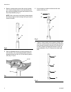
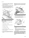
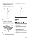
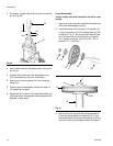
19. Screw the piston rod (23) and priming rod (34)
together aligning the pin hole in both pieces to allow
the pin to be pushed through (Fig. 20).
20. Replace the pin (8). Use a rubber hammer to tap the
pin into place, being careful to make sure the sides
of the pin are flush with the outside surface of the
piston rod (Fig. 20)
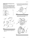
21. Check to make sure there is end play at all pinned
connections.
NOTE: When there is end play at the pinned connec-
tion, you should be able to slightly move from
side-to-side, the displacement rod (25) pinned to the
connecting rod (32) and the connecting rod (32) pinned
to the piston rod (23) and piston rod (23) pinned to the
priming rod (34).
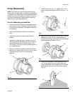
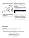
22. If these connections seem too rigid remove the pin
and adjust hole alignment by 1/2 turn in the direction
that aligns the through holes as close as possible,
axis-to-axis (Fig. 21).
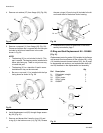
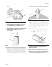
23. Install spacer cylinder (36) over rod assembly. Use
a strap wrench to tighten spacer cylinder securely.
24. Install cylinder (26) and seal (30). Torque to 45 - 55
ft. lbs (61 - 75 N.m).
25. Install the intake seal (28) over the end of the prim-
ing rod (34). Note the correct orientation of the
Fig. 19
Fig. 20
24
23
32
8
30
28
34
23
NOTICE
Improper alignment will take the self-aligning feature
out of the design which could result in damage to the
pump.
Fig. 21
Correct Alignment
Permits end play
Fig 3 - Correct
Fig 1 - 1/2 Turn Too Shallow
Incorrect Alignment
Fig 2 - 1/2 Turn Too Deep
Does not permit
end play
ti10469a
ti10468a
Does not permit
end play
ti10479a