


Instructions
8 3A1495C
6. Install the 5 screws (4) wrench tight only.
NOTE: If installing a new air cylinder (27), the mat-
ing holes are not threaded by design. Use thread
forming screws (4) to form threads as they are being
installed. Torque to 95-105 in.-lbs (10.7 - 11.8 N.m)
to ensure full thread formation.
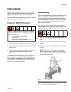
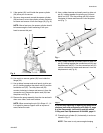
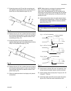
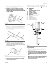
7. To ensure there is a proper seal between the air
valve and manifold, loosen all 5 screws (Fig. 16)
approximately 1/8 to 1/4 turn. These screws will be
torqued in Step 12, AFTER the air valve (40) is
installed.
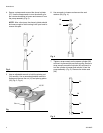
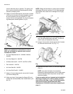
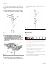
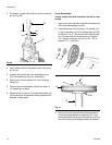
8. Secure pump assembly in a vise as shown in Fig.
17.
9. Perform any air valve repairs / maintenance
needed. See separate instruction manual included
with the related air valve repair kit.
10. Be sure seals (18) are lightly greased and installed
on air valve (40). Install air valve on air cylinder (21).
NOTE: The air valve (40) can be installed in any
configuration. There is not just one correct way to
install these parts.
11. Install screws (43). Torque to 60-70 in. lbs (6.8 - 7.9
N.m).
12. Torque screws (4) installed in Step 6 to 60-70 in. lbs
(6.8 - 7.9 N.m).
Muffler (17) Installation (Fig. 17)
13. Depending on your installation, the air valve (40)
can be mounted with the muffler (17) on either side
of the air valve.
To change the installation location:
a. Remove the 4 screws (43).
b. Remove the air valve (40) from its current
mounted position on the air cylinder (21) and
rotate the air valve 180 degrees, which will
reposition the muffler to face the other side of
the pump.
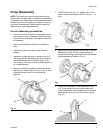
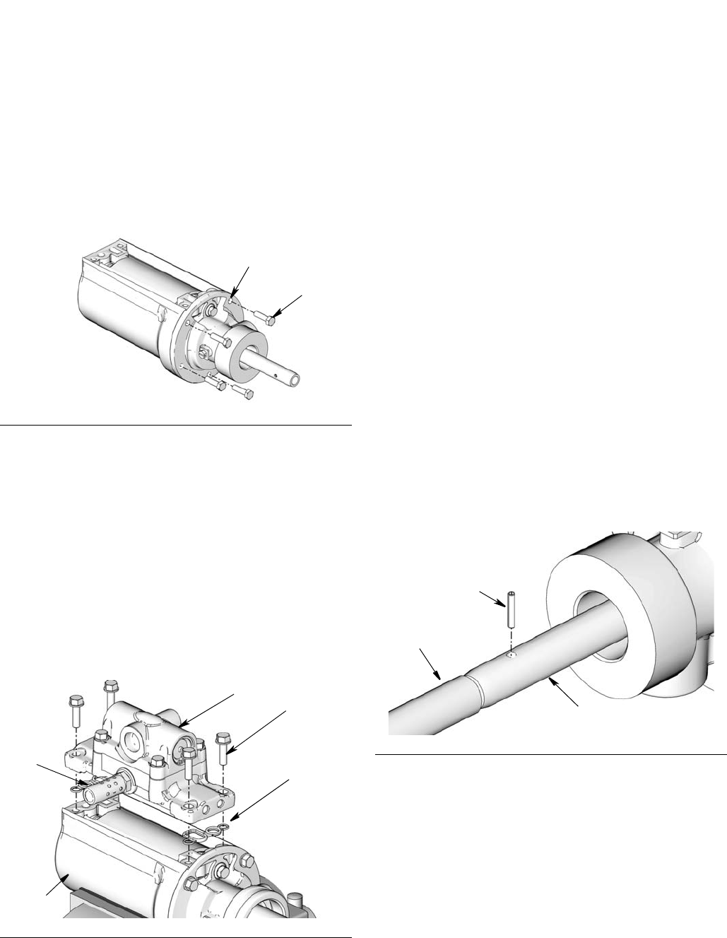
NOTE: When installing the pin (8) in Steps 14 - 20, it is
helpful to place a support, such as a piece of wood,
below the rods.
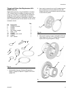
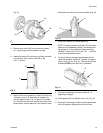
14. Screw the connecting rod (32) and the displacement
rod (25) together, aligning the pin hole in both
pieces to allow the pin to be pushed through (Fig.
18).
15. Replace the pin (8). Use a rubber hammer to tap the
pin into place, being careful to make sure the sides
of the pin are flush with the outside surface of the
connecting rod (Fig. 18).
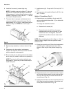
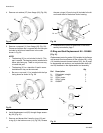
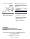
16. Install piston seal (24) over the end of the piston rod
(23). Note the correct orientation of the piston seal
on the piston rod as shown in Fig. 19.
Fig. 16
Fig. 17
4
14
43
40
21
18
17
Fig. 18
25
32
8