


Instructions
6 3A1495C
force to hold the pump in position. The pump cylin-
der is aluminum and could be damaged by using
excessive clamping force.
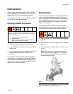
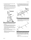
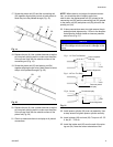
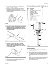
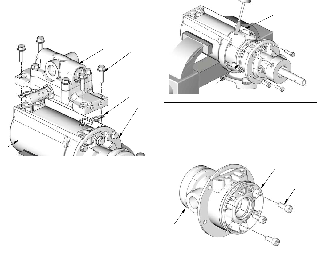
16. Using a 10 mm socket wrench, remove the 4 screws
(43) from the air valve (40) and completely remove
air valve assembly from air cylinder (21). Also
remove the two cover gaskets 18). If you are replac-
ing these parts, discard gaskets. (Fig. 9).
Repair and replacement instructions for the Air
Valve are included in a separate repair manual
included with the kit:
• Air Valve Replacement Kit - 24H848, 24H849,
24H850
• Air Valve Repair Kit - 24H798
• Air Motor Service Kit - 24J757, 24J758, 24J759
• Pilot Valve Kit - 24H749
• Air Valve Seal Kit - 24H851
• Air Valve End Cap Kit - 24H852
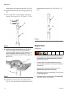
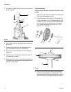
17. Using a 10 mm socket wrench, remove the 5 screws
(4) from the flange (22).
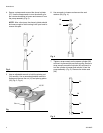
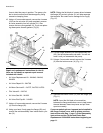
18. Using your hand, firmly grasp the flange (22) and
remove the entire assembly from inside the air cylin-
der (21).
NOTE: Sliding the flat blade of a screw driver between
the flange (22) and air cylinder (21) will help separate
the two parts. Be careful not to damage the o-ring (6)
(Fig. 10).
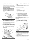
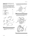
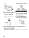
19. Pull the flange assembly off the displacement rod
(25). Set the displacement rod aside. You will not
need it until you reassemble the pump.
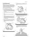
20. Using a 5 mm socket wrench remove the 3 screws
(3) from the bottom cover (14) (Fig. 11).
21. Separate the bottom cover (14) from the flange (22)
(Fig. 11).
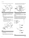
NOTE: Insert the flat blade of a screwdriver
between the flange and bottom cover to help loosen
the seal between these two pieces and pull them
apart more easily.
If you are replacing the o-rings and seals installed in
the flange, bottom cover, and air piston continue
instructions with Step 1, page 7 of the Reassembly
instructions and the Throat and Piston Seal
Replacement Kit 24H854 instructions beginning on
page 11.
Fig. 9
43
40
21
18
21
Fig. 10
Fig. 11
21
6
3
14
22