Max Model Setup
32 332305B
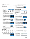
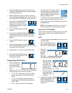
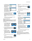
4. The cycle field is a 2 digit number.
When the correct first numeral of the
number displays, press the ENTER but-
ton to save the number. The cursor
automatically moves to the second number field.
NOTE: A leading zero (0) must be entered in the
first field if the number of cycles is fewer than 10.
5. Press the ENTER button, to save the C1
information.
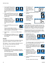
• If your G3 is equipped with
more than one sensor input,
you will automatically be
prompted to begin selecting
the pump control type for the
next sensor. Repeat steps 1 - 5 to program cycles
for C2 and C3.
NOTE: If C / P2 and C / P3 are not used, the default
OFF setting must be entered instead.
6. After you set the last field and press the
ENTER button, the G3 saves the Cycle
information and moves to setting
Backup Time, page 34.
Pressure Control (P1, P2, P3) Setup
• For injector systems, monitoring pressure can be
used as a way to ensure sufficient pressure has
been reached to activate injectors. The pump runs,
building up enough pressure to cause injectors to
dispense fluid. Pressure continues to build to a pre-
set maximum, activating the (user supplier) pres-
sure switch. Then an external (user supplied) vent
valve opens and pressure reduces, priming the
injector for the next cycle.
• Pressure control is an ON / OFF selection only.
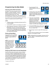
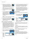
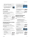
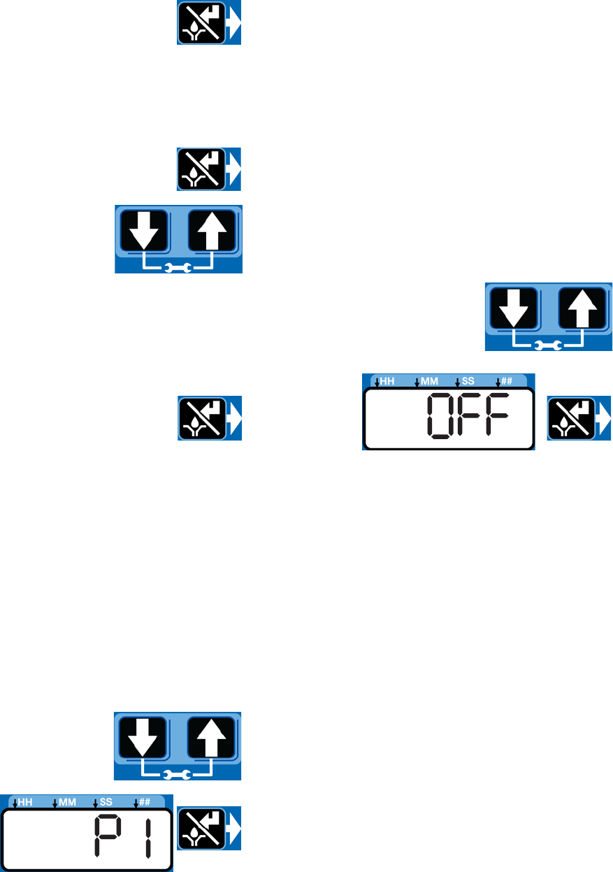
1. Use the UP or DOWN arrow
button to toggle between OFF
/ C1/ P1.
2. When P1
displays,
press
ENTER
button to
save
selection.
3. If your G3 comes equipped with more than one sen-
sor input, you will automatically be prompted to
begin selecting pump control type for the next sen-
sor. Repeat steps 1 - 2 to program P2 and P3.
If P1 / P2 / P3 is selected the vent valve time is
automatically set to 5 minutes. If the unit is used in
an injector based system and a sensor input is not
used, the user must update the vent valve time in
advanced programming. (See Advanced Program-
ming, A-3 Vent Valve Time, page 47.)
Input Not Used
Select OFF if your system does not use the applicable
input.
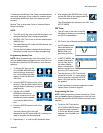
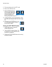
1. Use UP or DOWN arrow but-
ton to toggle between OFF /
C1 / P1 on the display.
2. When
OFF is on
the dis-
play,
press the
ENTER
button to save selection.
If the sensor inputs are available and none are used in
the ON Mode, the definition of the entered time is ON
TIME.
Examples:
Model G3-G-24MX-2LFL00-1DMVA2R3 has 4 sensors,
so C/P1, C/P2, and C/P3 and Machine Count can all be
programmed.
Model G3-G-24MX-2LFL00-10CV00R0 has 1 sensor,
only C/P1 is available for programming.
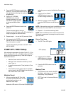
Backup Time
In both Cycle and Pressure Modes, a maximum run
Time (Backup Time) for the lubrication period must be
set up. If this Time expires before the lubrication is com-
pleted an alarm/warning is triggered and the pump
stops.


