


5308981
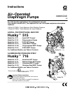
Installation
Air Line
WARNING
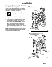
A bleed-type master air valve (B) is required in your
system to relieve air trapped between this valve
and the pump. See Fig. 2. Trapped air can cause
the pump to cycle unexpectedly, which could result
in serious injury, including splashing in the eyes or
on the skin, injury from moving parts, or contamina-
tion from hazardous fluids.
CAUTION
The pump exhaust air may contain contaminants.
Ventilate to a remote area if the contaminants could
affect your fluid supply. Read Air Exhaust Ventila-
tion on page 6.
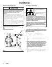
1. Install the air line accessories as shown in Fig. 2.
Mount these accessories on the wall or on a
bracket. Be sure the air line supplying the acces-
sories is electrically conductive.
a. The fluid pressure can be controlled in either
of two ways. To control it on the air side, install
an air regulator (G). To control it on the fluid
side, install a fluid regulator (J) near the pump
fluid outlet (see Fig. 2).
b. Locate one bleed-type master air valve (B)
close to the pump and use it to relieve trapped
air. Read the WARNING above. Locate the
other master air valve (E) upstream from all air
line accessories and use it to isolate them
during cleaning and repair.
c. The air line filter (F) removes harmful dirt and
moisture from the compressed air supply.
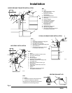
2. Install an electrically conductive, flexible air hose
(C) between the accessories and the 1/4 npt(f)
pump air inlet. Use a minimum 1/4 in. (6.3 mm) ID
air hose. Screw an air line quick disconnect cou-
pler (D) onto the end of the air hose (C), and
screw the mating fitting into the pump air inlet
snugly. Do not connect the coupler (D) to the fitting
yet.
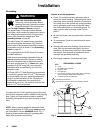
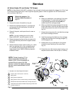
Installation of Remote Pilot Air Lines
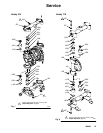
1. Refer to Parts Drawings. Connect air line to pump
as in preceding steps.
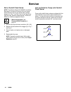
2. Connect 1/4 in. O.D. tubing to push type connec-
tors (16) on underside of pump.
NOTE: by replacing the push type connectors, other
sizes or types of fittings may be used. The new fittings
will require 1/8 in. npt threads.
3. Connect remaining ends of tubes to external air
signal, such as Graco’s Cycleflo (P/N 195264) or
Cycleflo II (P/N195265) controllers.
NOTE: the air pressure at the connectors must be at
least 30% of the air pressure to the air motor for the
pump to operate.
Fluid Suction Line
D If using a conductive (acetal) pump, use conductive
hoses. If using a non-conductive pump, ground the
fluid system. Read Grounding on page 8. The
fluid inlet port is 1/2 in. or 3/4 in.
D At inlet fluid pressures greater than 15 psi
(0.1 MPa, 1 bar), diaphragm life will be shortened.
Fluid Outlet Line
WARNING
A fluid drain valve (H) is required in your system to
relieve pressure in the hose if it is plugged. See
Fig. 2. The drain valve reduces the risk of serious
injury, including splashing in the eyes or on the
skin, or contamination from hazardous fluids when
relieving pressure. Install the valve close to the
pump fluid outlet.
1. Use electrically conductive fluid hoses (K). The
pump fluid outlet is 1/2 in. or 3/4 in. Screw the fluid
fitting into the pump outlet snugly. Do not over-
tighten.
2. Install a fluid regulator (J) at the pump fluid outlet
to control fluid pressure, if desired (see Fig. 2).
See Air Line, step 1a, for another method of
controlling pressure.
3. Install a fluid drain valve (H) near the fluid outlet.
Read the WARNING above.