


14 308981
Service
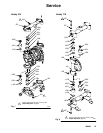
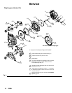
Ball or Duckbill Check Valves
NOTE: Fluid Section Repair Kit D05XXX is available.
See page 22 to order the correct kit for your pump.
Parts included in the kit are marked with a double
dagger (}) in Fig. 7 and Fig. 8 and in the Parts Draw-
ings and Lists. General purpose grease 111920 and
Adhesive 113500 are supplied in the kit.
1. Relieve the pressure. See
Pressure Relief Procedure on
page 10.
2. Remove the top and bottom manifolds (102, 103).
3. Remove all parts shown with a dagger (}) in Fig. 7
and Fig. 8.
4. Clean all parts, and replace worn or damaged
parts.
5. Reassemble the pump.
NOTE: Torque the manifold nuts (109) or bolts
(105) to 80 to 90 in-lb (9 to 10 NSm). See Torque
Sequence, page 29.
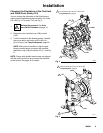
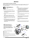
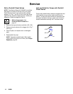
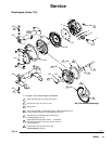
Inlet and Outlet for Pumps with Duckbill
Check Valves
Pumps with duckbill check valves are shipped with the
inlet manifold on top and the outlet manifold on the
bottom. To make the inlet manifold on the bottom and
the outlet manifold on the top, rotate each of the four
duckbill assemblies vertically 180_ as shown below.
}202
}201
}139
9080A