


13308981
Service
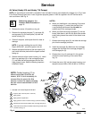
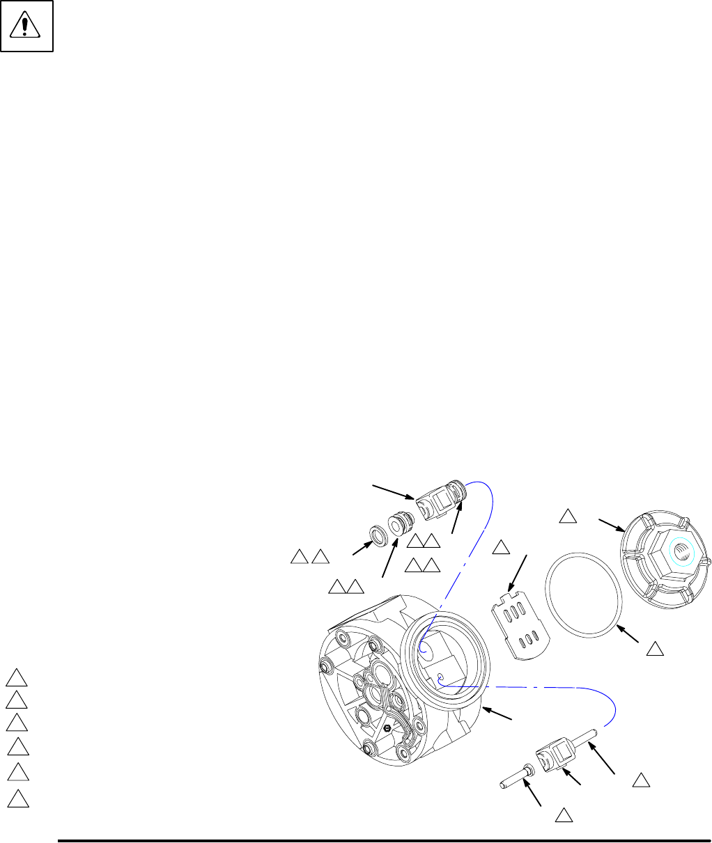
Air Valve (Husky 515 and Husky 716 Pumps)
NOTE: Air Valve Repair Kit 241657 is available. Parts included in the kit are marked with a dagger ({) in Fig. 6 and
in the Parts Drawings and Lists. A tube of general purpose grease 111920 is supplied in the kit. Service the air
valve as follows. See Fig. 6.
1. Relieve the pressure. See
Pressure Relief Procedure on
page 10.
2. Remove the cover (10) and the o-ring (4).
3. Remove the carriage plungers (7), carriages (8),
carriage pins (9), and valve plate (14) from the
center housing (11).
4. Clean all the parts, and inspect them for wear or
damage.
NOTE: If you are installing the new Air Valve
Repair Kit 241657, use all the parts in the kit.
5. Grease the lapped surface of the valve plate (14),
and install the valve plate with the lapped surface
facing up.
6. Grease the bores of the center housing (11), install
the u-cup packings (2) on the carriage plungers
(7), and slide the carriage plungers into the car-
riage plunger bores. See the following important
installation notes:
NOTES:
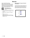
D When you install each u-cup packing (2) on each
carriage plunger (7), make sure the lips of the
u-cup packing face toward the clip end (the
smaller end) of the carriage plunger.
D When you slide the carriage plungers (7) into the
bores, slide them in with the clip ends (the smaller
ends) facing toward the center of the center hous-
ing (11).
7. Grease the carriage pins (9), and slide the carriage
pins into the carriage pin bores.
8. Install the carriages (8). Make sure the carriages
engage the clip ends of the carriage plungers (7)
and carriage pins (9).
9. Grease the o-ring (4), and seat it in the groove
around the cover opening of the center hous-
ing (11).
10. Screw the cover (10) into the center housing, and
torque the cover to 80 to 100 in-lb (9.0 to 13.6 N-m).
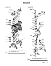
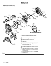
Fig. 6
1
2
Torque to 80 to 100 in-lb (9.0 to 13.6 N-m).
Apply grease.
9{
14{
{2
{8
{7
9{
8{
2{
7{
4
10
1
Apply grease to lapped face.3
3
Apply grease to bores of center housing (11) before installing.
4
4
4
2
11
2
2
{ Included in Air Valve Repair Kit 241657
Seal lips face clip end (the smaller end) of carriage plunger (7).
5
5
5
Install with the clip ends (the smaller ends) facing toward center
of center housing (11).
6
NOTE: Center housing (11) is
shown separated from the air
covers, but it is not necessary to
remove the air covers for this
service. Leave the center housing
and air covers assembled for this
service.
9069A
4 6
4 6