


SS-GMV95 www.goodmanmfg.com 5
PRODUCT SPECIFICATIONS
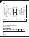
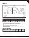
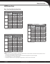
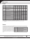
GCV9 DIMENSIONS
FOLDED FLANGES
UNFOLDED FLANGES
FOLDED FLANGES
UNFOLDED FLANGES
Model A B C D E
GCV90704CXB
21” 19½” 16⅛” 18” 19½”
GCV90905DXB
24½” 23” 20⅝” 21½” 23”
GCV91155DXB 24½” 23” 20⅝” 21½” 23”
Notes:
• Installer must supply one or two PVC pipes: one for combustion air (optional) and one for the fl ue outlet (required). Vent pipe must be
either 2” or 3” in diameter, depending upon furnace input, number of elbows, length of run, and installation (1 or 2 pipes). The optional
Combustion Air Pipe is dependent on installation/code requirements and must be 2” or 3” diameter PVC.
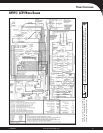
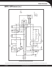
• Line voltage wiring can enter through the right or left side of the furnace. Low-voltage wiring can enter through the right or left side of
furnace.
• Conversion kits for high-altitude natural gas operation are available. Contact your Goodman distributor or dealer for details.
• Installer must supply following gas line fi ttings, according to which entrance is used:
Left—Two 90º Elbows, one close nipple, straight pipe
Right—Straight pipe to reach gas valve
• For bottom return: Failure to unfold fl anges may reduce airfl ow by up to 18%. This could result in performance and noise issues.
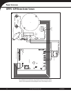
MINIMUM CLEARANCES TO COMBUSTIBLE MATERIALS
Position Sides Rear Front Bottom Flue Top
Downfl ow 0” 0” 3” NC 0” 1”
Horizontal 6” 0” 3” C 0” 6”
C = If placed on combustible fl oor, the fl oor MUST be wood ONLY.
NC = For installation on non-combustible fl oors only. A combustible fl oor sub-base must be used for installations on combustible fl ooring.
Notes:
• For servicing or cleaning, a 24” front clearance is required.
• Unit connections (electrical, fl ue and drain) may necessitate greater clearances than the minimum clearances listed above.
• In all cases, accessibility clearance must take precedence over clearances from the enclosure where accessibility clearances
are greater.