


8
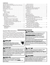
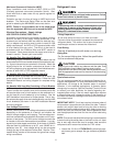
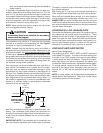
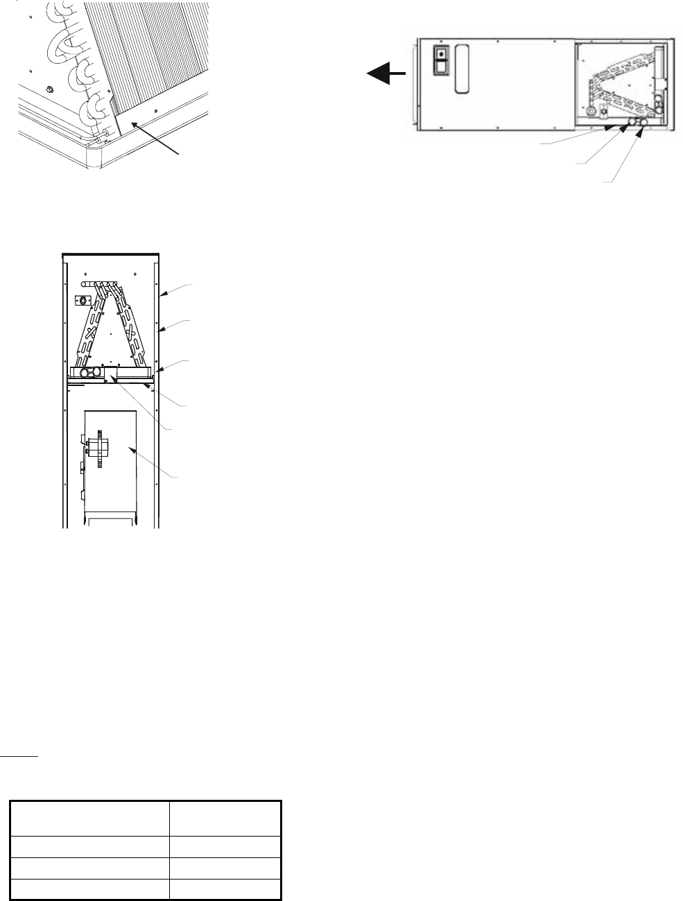
3” FLAT INSULATION
RETAINER
(BOTH SIDES)
Figure 4
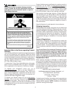
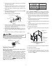
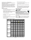
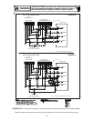
To complete the conversion, slide the evaporator coil into
the chassis and attach the three (3) access panels. (Figure
5).
WRAPPER
INSULATION
JACKET
ZEE COIL
SUPPORT
WRAPPER
STIFFENER
DRAIN PAN
INSULATION KIT
BLOWER
A
SSEMBLY
Figure 5
NOTE: When converted to downflow position, the coil may
protrude above the cabinet on some models.
Horizontal Conversion
Dedicated Downflow models are not suitable for horizontal
application and must not be used for this type of installation.
The only field modification required for conversion to “Hori-
zontal Right-Hand” is the removal of the plastic knockouts in
the horizontal panel drain connections. To prevent the hori-
zontal drain pan from sweating in high humidity applications,
it is recommended that a DPIH insulation accessory kit be
used. NOTE: The DPIH insulation kit is not supplied with this
product and should be purchased separately. See Table 8
for the correct DPIH kit.
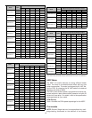
ARUF, ATUF
or ARPF Model
Insulation Kit
1729 / 1824 DPIH18-32
3030 / 1931 / 3636 DPIH36-42
3642 / 3743 / 4860 / 4961 DPH48-61
Table 8
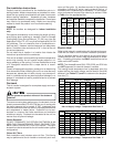
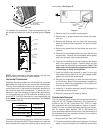
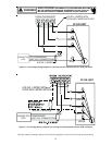
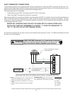
The following describes converting to “Horizontal Left-Hand”.
Conversion to downflow MUST be performed in an area that
allows access to all sides prior to placing the air handler in its
final location (See Figure 6).
PRIMARY
DRAIN
SECONDARY
DRAIN
DPIH KIT
Figure 6
1. Remove the (3) air handler access panels.
2. Remove the “J” shaped bracket that retains the evapo-
rator coil.
3. Remove the flowrator from the lower left side access
panel and slide out the evaporator coil and horizontal
drain pan.
4. Remove the gasket from the horizontal pan drain con-
nections.
5. Remove the oval shaped plastic plug from the left side
access panel. Remove the oval shaped rubber gasket
seal from the lower right side access panel.
6. The drain connections for the horizontal pan are sealed
with a thin coating of plastic. Carefully knock out this
plastic seal with a screwdriver and hammer. Note: The
upper drain will become the secondary drain which
is mandatory in many municipalities .
7. Install the plastic plug removed in step 5 to the right
side lower access panel and the oval shaped rubber
gasket to the lower left access panel.
8. Reinstall the evaporator coil with the horizontal panel
on the left side. Note: Push the assembly completely to
the rear to ensure the engagement of the upflow pan
with the rear channel bracket.
9. Install the “J” bracket (removed in step 2) to support the
upflow pan to the tie channel.
10. Attach all panels and the metering device.
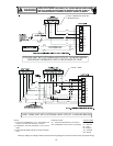
Condensate Removal
The coil drain pan has a primary and an optional secondary
drain with 3/4" NPT female connections. The connectors re-
quired can be 3/4" NPT male either PVC, CPVC or metal
pipe and should be hand tightened to a torque of approxi-
mately 37 in-lbs. to prevent damage to the drain pan connec-
tion. An insertion depth between .355 to .485 inches (3-5
turns) should be expected at this torque. Use the female (3/4
fpt) threaded fitting that protrudes outside of the enclosure
for external connections.
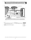
1. Ensure drain pan hole is NOT obstructed.
2. To prevent potential sweating and dripping on to finished
space, it may be necessary to insulate the condensate