


6
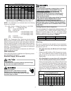
Maximum Overcurrent Protection (MOP)
Every installation must include an NEC (USA) or CEC
(Canada) approved overcurrent protection device. Also,
check with local or state codes for any special regional re-
quirements.
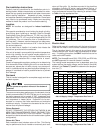
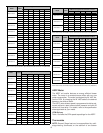
Protection can be in the form of fusing or HACR style circuit
breakers. The Series and Rating Plate can be used as a
guide for selecting the MAXIMUM overcurrent device.
NOTE: Fuses or circuit breakers are to be sized larger
than the equipment MCA but not to exceed the MOP.
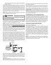
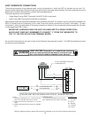
Electrical Connections – Supply Voltage
USE COPPER CONDUCTORS ONLY.
A knockout is provided on the air handler top panel or side to
allow for the entry of the supply voltage conductors. If the
knockouts on the cabinet sides are used for electrical con-
duit, an adapter ring must be used in order to meet UL1995
safety requirements. An NEC or CEC approved strain relief
is to be used at this entry point. The wire is to be sized in
accordance with the “Electrical Wire and MOP” section of
this manual. Some areas require the supply wire to be en-
closed in conduit. Consult your local codes.
Air Handler Only (Non-Heat Kit Models)
The building supply connects to the stripped black and red
wires contained in the air handler electrical compartment cav-
ity. A ground screw is also contained in this area. Attach the
supply wires to the air handler conductors as shown in the
unit wiring diagram using appropriately sized solderless con-
nectors or other NEC or CEC approved means.
Air Handler With Non-Circuit Breaker Heat Kits
A terminal block is provided with the HKR kit to attach the
power supply and air handler connections. Follow the HKR
Installation Manual and wiring diagram for complete wiring
details.
Air Handler With Heat Kits Containing a Circuit Breaker
HKR models with a “C” suffix contain a circuit breaker(s).
The air handler has a plastic cover on the access panel that
will require either one or both sections to be removed to al-
low the heat kit circuit breaker(s) to be installed. See the
HKR Installation Instructions for further details. The air han-
dler wires and supply wires are installed directly onto the HKR
circuit breaker(s) as shown in the HKR Installation Manual
and wiring diagram.
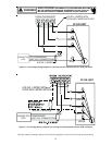
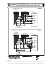
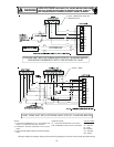
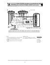
Low Voltage Connections
Several combinations of low voltage schemes are available,
depending on the presence of a heat kit and whether the
heat kit is single-stage or multi-staging. The low voltage con-
nections are determined by whether the outdoor unit is a con-
denser or heat pump. The 24V-control voltage connects the
air handler to the room thermostat and condenser. Low volt-
age wiring is to be copper conductors. A minimum of 18AWG
must be used for installations up to 50’ and 16AWG for in-
stallations over 50’. Low voltage wiring can be connected
through the top of the cabinet or either side. See the “Ther-
mostat Wiring” section of this manual for typical low voltage
wiring connections.
Refrigerant Lines
This product is factory-shipped under pressure. Follow
these instructions to prevent injury.
A quenching cloth is strongly recommended to prevent
scorching or marring of the equipment finish when
welding close to the painted surfaces. Use brazing
alloy of 5% minimum silver content.
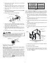
Tubing Preparation
All cut ends are to be round, burr free, and clean.
Failure to follow this practice increases the chances for
refrigerant leaks. The suction line is spun closed and
requires pipe cutters to remove the closed end.
Post Brazing
Quench all welded joints with water or a wet rag.
Piping Size
For the correct tubing size, follow the specification
for the condenser/heat pump.
Applying too much heat to any tube can melt the tube. Torch
heat required to braze tubes of various sizes must be
proportional to the size of the tube. Service personnel must
use the appropriate heat level for the size of the tube being
brazed.
CAUTION
Special Instructions
This coil comes equipped with a check style flowrator for re-
frigerant management. For most installations with matching
applications, no change to the flowrator piston is required.
However, in mix-matched applications, a flowrator piston
change may be required. See the Goodman
®
piston kit chart
or consult your local distributor for details regarding mix-
matched piston sizing. If the mix-match application requires
a different piston size, change the piston in the flowrator on
the indoor coil before installing the coil and follow the proce-
dure shown below.
IMPORTANT NOTE: Torch heat required to braze tubes of
various sizes is proportional to the size of the tube. Tubes of
smaller size require less heat to bring the tube to brazing
temperature before adding brazing alloy. Applying too much
heat to any tube can melt the tube. Service personnel must
use the appropriate heat level for the size of the tube being
brazed.
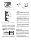
NOTE: The use of a heat shield when brazing is recommended
to avoid burning the serial plate or the finish on the unit. Heat
trap or wet rags should be used to protect heat sensitive
components such as service valves and TXV valves.
1. Loosen the 13/16 nut 1 TURN ONLY to allow high pres-
sure tracer gas to escape. No gas indicates a possible
leak.