


4
Pre-Installation Instructions
Carefully read all instructions for the installation prior to in-
stalling product. Make sure each step or procedure is under-
stood and any special considerations are taken into account
before starting installation. Assemble all tools, hardware
and supplies needed to complete the installation. Some items
may need to be purchased locally. Make sure everything
needed to install the product is on hand before starting.
Location
NOTE: Air handlers are designed for indoor installation
only.
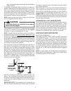
Give special consideration to minimizing the length of refrig-
erant tubing when installing air handlers. Refer to Remote
Cooling/Heat Pump Service Manual, TP-106 Long Line Set
Application R-22 or TP-107 Long Line Set Application R-410A
for guidelines. The unit clearance from a combustible sur-
face may be 0". However, service clearance is to take prece-
dence. In addition allow a minimum of 24" in front of the unit
for service clearance.
Do not install the air handler in a location that violates the
instructions provided with the condenser.
If the unit is located in an area with high ambient temperature
and/or high humidity the air handler maybe subject to nui-
sance sweating of the casing. On these installations a wrap
of 2” fiberglass insulation with a vapor barrier is recom-
mended.
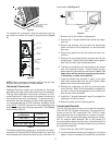
Consult all appropriate regulatory codes prior to determining
final clearances. When installing this unit in an area that may
become wet, elevate the unit with a sturdy, non-porous ma-
terial. In installations that may lead to physical damage (i.e. a
garage) it is advised to install a protective barrier to prevent
such damage.
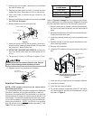
Ductwork
This air handler is designed for a complete supply and return
ductwork system.
Do not operate this product without all the ductwork
attached.
To ensure correct system performance, the ductwork is to be
sized to accommodate 375-425 CFM per ton of cooling with
the static pressure not to exceed .5" WC. Inadequate duct
work that restricts airflow can result in improper performance
and compressor or heater failure. Ductwork is to be con-
structed in a manner that limits restrictions and maintains
suitable air velocity. Ductwork is to be sealed to the unit in a
manner that will prevent leakage.
Return Ductwork
DO NOT TERMINATE THE RETURN DUCTWORK IN AN
AREA THAT CAN INTRODUCE TOXIC, OR OBJECTION-
ABLE FUMES/ODORS INTO THE DUCTWORK. The return
ductwork is to be introduced into the air handler bottom (upflow
configuration).
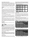
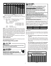
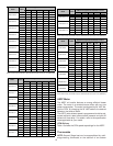
Return Air Filters
Each installation must include a return air filter. This filtering
may be performed at the air handler or externally such as a
return air filter grille. Air handlers mounted in the downflow
orientation, including “B” series, require external filtering. A
washable filter is available as an accessory. To ensure opti-
mum performance frequent filter cleaning is advised. Refer
to Table 1 for the appropriate filter.
ATUF
ARUF
ARPF
ADPF ASPF
Filter
Number
Qty
Required
1729
1824
3030 3030
1931 1931
3636 3636
3642 3642 3042 3036
3743 3743 3137
4860 4860 4860 4260
1
FIL 48-61 1
3030 1830 FIL 36-42 1
1824 1824 N/A FIL 18-32
Table 1
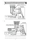
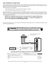
Electric Heat
Refer to this manual in combination with the instructions pro-
vided with the heat kit for the correct installation procedure.
The air handlers listed in this manual do not have factory
installed electric heat. Electric heat is available as an acces-
sory. If installing this option, the ONLY heat kits that can be
used are the HKR series.
NOTE: The Amana® brand EHK, ECB, EDB, and EDK kits
are NOT approved for use with these air handlers.
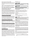
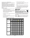
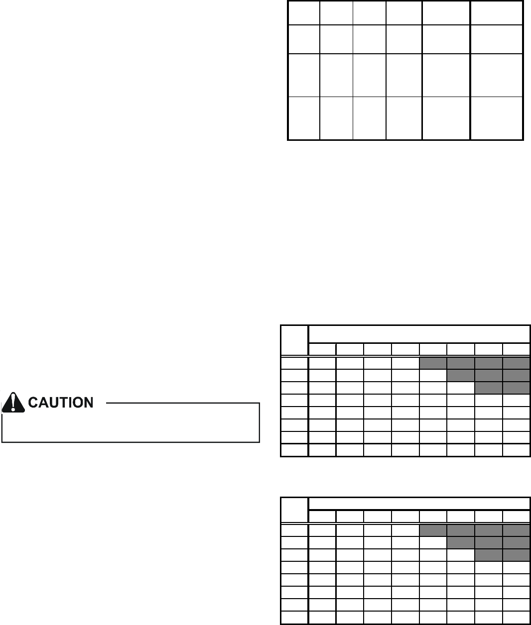
The heating mode temperature rise is dependent upon the
system airflow, the supply voltage, and the heat kit size (kW)
selected. Use Tables 2, 3, and 4 to determine the tempera-
ture rise (
º
F).
356810152021
600 18 28 35 41
800 13 21 26 31 42
1000 11 17 21 25 34 50
12009 14182128425662
14008 12151824364853
16007 10131521314246
1800 6 9 12 14 19 28 37 41
2000 5 8 11 12 17 25 34 37
HEAT KIT NOMINAL kW
CFM
Table 2
230/1/60 Supply Voltage - Temperature Rise Table °F
356810152021
600 17 27 34 39
800 13 20 25 30 40
1000 10 16 20 24 32 48
12008 13172027405359
14007 11141723344651
16006 10131520304044
1800 6 9 11 13 18 27 36 39
2000 5 8 10 12 16 24 32 35
CFM
HEAT KIT NOMINAL kW
Table 3
220/1/60 Supply Voltage - Temperature Rise Table °F