


7
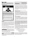
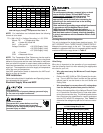
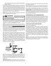
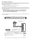
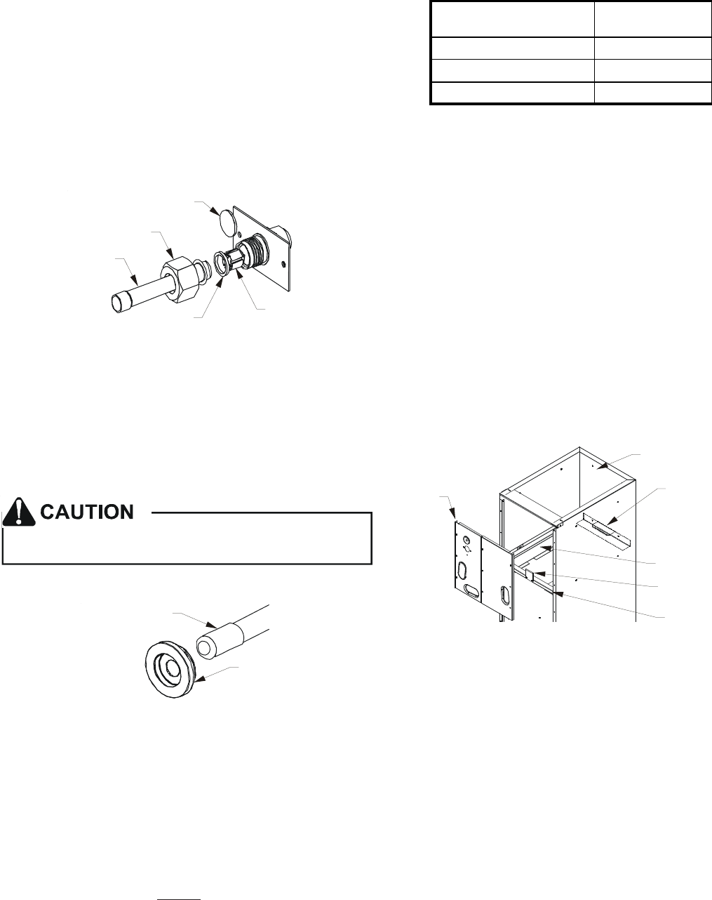
2. After the gas has escaped, remove the nut and discard
the black or brass cap.
3. Remove the check piston to verify it is correct and then
replace the piston. See piston kit chart in instructions.
4. Use a tube cutter to remove the spin closure on the
suction line.
5. Remove the tailpiece clamped to the exterior and slide
the 13/16 nut into place.
6. Braze tailpiece to the line set liquid tube.
WHITE
TEFLON SEAL
PISTON
TAILPIECE
13/16” NUT
PLASTIC or BRASS CAP
Figure 1
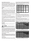
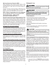
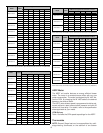
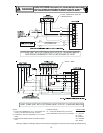
7. Insert the suction line into the connection, slide the in-
sulation and the rubber grommet at least 18" away from
the braze joint. Braze suction line.
8. AFTER THE TAILPIECE HAS COOLED, confirm posi-
tion of the white Teflon
®
seal and hand tighten the 13/
16 nut.
9. Torque the 13/16 nut to 10-25 ft-lbs. or tighten 1/6 turn.
Excessive torque can cause orifices to stick. Use the
proper torque settings when tightening orifices.
10. Replace suction line grommet and insulation.
RUBBER
GROMMET
SUCTION LINE
WITH SPIN CLOSURE
Figure 2
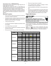
Downflow Conversion
NOTE: ATUF models should not be converted to
Downflow applications.
“D” nomenclature models are factory equipped for “Dedicated
Downflow” operation and no field conversion is required.
Conversion to downflow MUST be performed in an area that
allows access to all sides prior to placing the air handler in its
final location. To prevent the evaporator coil pan from “sweat-
ing” the DPI accessory insulation kit is to be used when per-
forming this conversion. NOTE: The DPI kit is not supplied
with this product and is to be purchased separately. See
Table 7 for the correct DPI kit.
ARUF, ATUF
or ARPF Model
Insulation Kit
1729 / 1824 DPI18-30/20
3030 / 1931 / 3636 DPI36-42/20
3642 / 3743 / 4860 / 4961 DPI48-61/20
Table 7
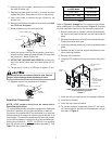
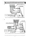
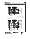
Refer to Figures 3 through 5 for the location of the compo-
nents referenced in the following steps. Figure 3 illustrates
the new installation location for the removed components.
1. Before inverting the air handler, remove all access pan-
els, the coil rear channel bracket, and the filter close-off
panel.
2. Remove the evaporator coil and the horizontal drain pan.
Discard horizontal drain pan.
3. Install the provided plastic plug into the vacated access
panel.
4. Remove the two (2) zee coil support brackets and insu-
lation retaining brackets.
5. Remove the tie bracket.
6. Install the DPI Insulation Kit onto the bottom of the drain
pan.
NOTE: The filter provision is not applicable
in THIS downflow application.
ACCESS
PANEL
RETURN AIR SIDE
OF UNIT
REAR CHANNEL
BRACKET
ZEE COIL
SUPPORT BRACKET
COIL RETAINING
BRACKET
TIE BRACKET
Figure 3
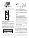
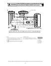
7. Install the zee coil supports and the wrapper stiffeners.
8. Install the tie bracket.
9. Install the rear channel bracket.
10. To prevent possible condensate “blow off” the insula-
tion retainers are to be laid into the evaporator coil pan
as shown in Figure 4.