


5
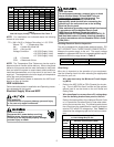
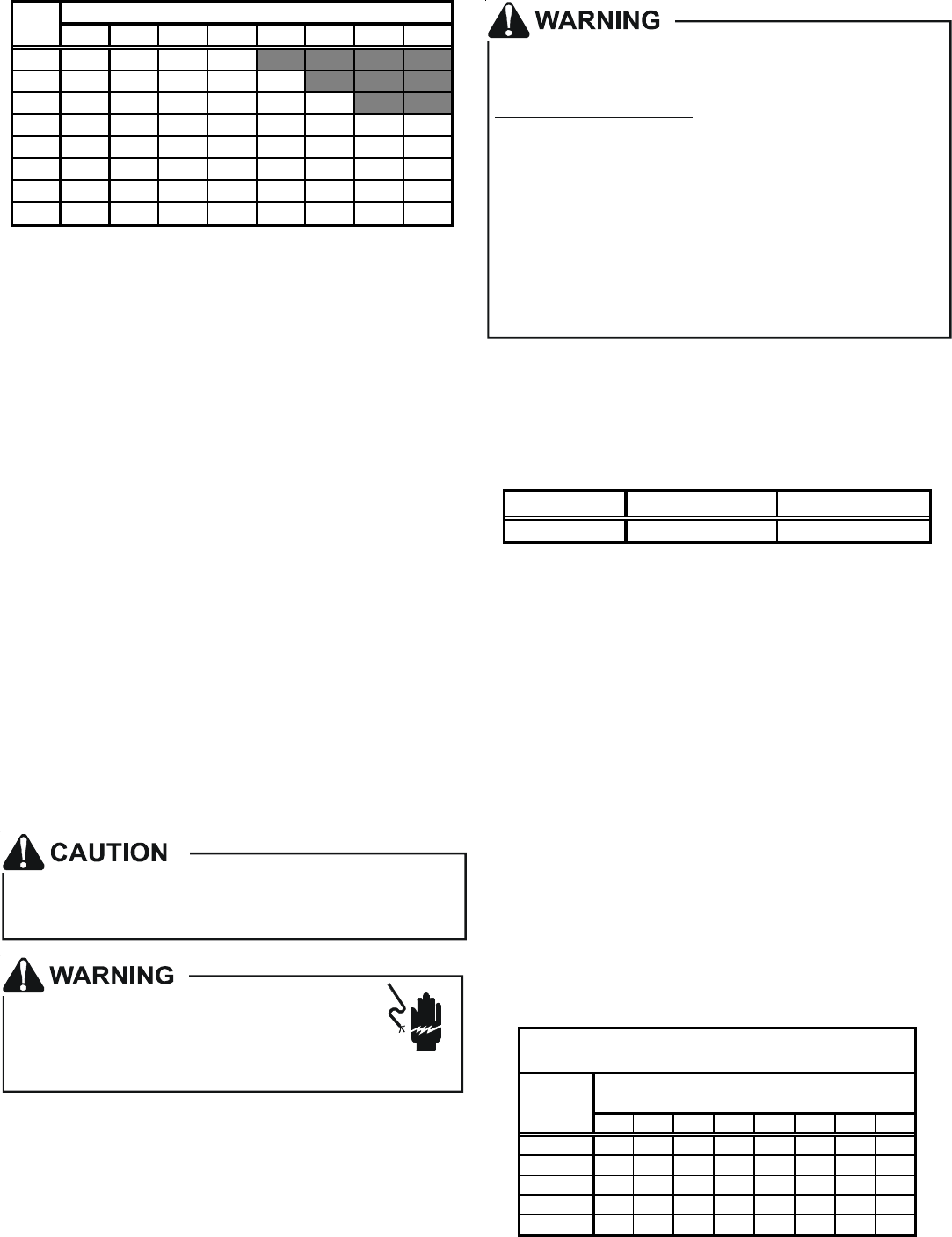
356810152021
600 16 25 32 37
800 12 19 24 38 38
1000 10 15 19 22 30 46
12008 13161925385156
14007 11141622334348
1600 6 9 12 14 19 28 38 42
1800 5 8 11 12 17 25 34 37
2000 5 8 10 11 15 23 30 34
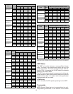
CFM
HEAT KIT NOMINAL kW
Table 4
208/1/60 Supply Voltage - Temperature Rise Table °F
NOTE: For installations not indicated above the following
formula is to be used:
TR = (kW x 3412) x (Voltage Correction) x 1.08 / CFM
Where: TR = Temperature Rise
kW = Heater Kit Actual kW
3412 = Btu per kW
Voltage Correction =.96 (230 Supply Volts)
=.92 (220 Supply Volts)
=.87 (208 Supply Volts)
1.08 = Constant
CFM = Measured Airflow
NOTE: The Temperature Rise Tables can also be used to
determine the air handler airflow delivery. When using these
tables for this purpose set the room thermostat to maximum
heat and allow the system to reach steady state conditions.
Insert two thermometers, one in the return air and one in the
supply air. The temperature rise is the supply air temperature
minus the room air temperature.
Use HKR specification sheets to determine the HKR avail-
able for a given air handler.
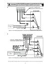
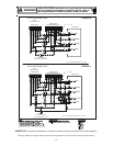
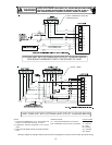
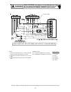
HKR Installation
Follow instructions listed in Installation and Operating Instruc-
tions shipped with the heat kit.
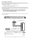
Electrical Supply Wire and MOP
FIRE HAZARD!
To avoid the risk of property damage, personal injury
or fire, use only copper conductors.
HIGH VOLTAGE!
Failure to do so may cause property damage,
personal injury or death.
Disconnect ALL power before servicing.
Multiple power sources may be present.
HIGH VOLTAGE!
To avoid property damage, personal injury or death
due to electrical shock, this unit MUST have an
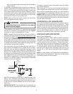
electrical ground. The
electrical ground circuit may consist of an
appropriately sized electrical wire connecting the
ground lug in the unit control box to the building
electrical service panel.
Other methods of grounding are permitted if performed
in accordance with the National Electric Code
(NEC)/American National Standards Institute
(ANSI)/National Fire Protection Association (NFPA) 70
and local/state codes. In Canada, electrical grounding
is to be in accordance with the Canadian Electric Code
(CSA) C22.1.
uninterrupted, unbroken
Building Electrical Service Inspection
This unit is designed for single-phase electrical supply. DO
NOT OPERATE ON A THREE-PHASE POWER SUPPLY.
Measure the power supply to the unit. The supply voltage
must be in agreement with the unit nameplate power require-
ments and within the range shown in Table 5.
Nominal Input Minimum Voltage Maximum Voltage
208/240 187 253
Table 5
Wire Sizing
Wire size is important to the operation of your equipment.
Use the following check list when selecting the appropriate
wire size for your unit.
• Wire size must carry the Minimum Circuit Ampac-
ity (MCA).
• Refer to the NEC (USA) or CSA (Canada) for wire siz-
ing. The unit MCA for the air handler and the optional
electric heat kit can be found on the unit Series and
Rating Plate.
• Wire size allows for no more than a 2% voltage drop
from the building breaker/fuse panel to the unit.
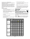
Refer to the latest edition of the National Electric Code
or in Canada the Canadian Electric Code when deter-
mining the correct wire size. The following table shows
the current carrying capabilities for copper conductors
rated at 75
o
C with a 2% voltage drop. Use Table 6 to
determine the voltage drop per foot of various conduc-
tors.
10 15 20 25 30 35 40 45
14 75 50 37 NR NR NR NR NR
12 118 79 59 47 NR NR NR NR
10 188 125 95 75 63 54 NR NR
8 301 201 150 120 100 86 75 68
6 471 314 235 188 157 134 118 110
*Based on NEC 1996
Maximum Allowable Length in Feet
to Limit Voltage Drop to 2%*
Minimum Circuit Ampacity (MCA)
Wire Size
(AWG)
Table 6