


17
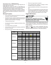
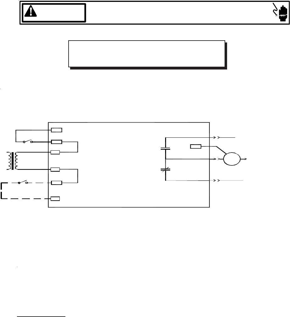
HIGH VOLTAGE!
DISCONNECT ALL POWER BEFORE SERVICING.
MULTIPLE POWER SOURCES MAY BE PRESENT. FAILURE TO DO SO
MAY CAUSE PROPERTY DAMAGE, PERSONAL INJURY OR DEATH.
WARNING
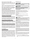
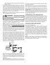
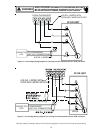
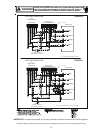
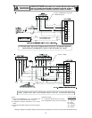
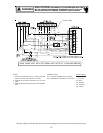
Wiring is subject to change. Always refer to the wiring diagram on the unit for the most up-to-date wiring.
120/240VACTSTAT
OPTIONAL
SPEEDUP
24 VAC
SYSTEM
TRANSFORMER
C
SPEEDUP
XFMR-C
XFMR-R
R
B13707-35
WIRING DIAGRAM
M1
PARK TERMINAL
K1
K1
FOR USE WITH
NEUTRAL
G
HEAT KIT
MOTOR
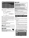
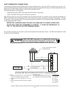
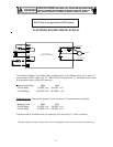
The Electronic Blower Time Delay Relay provides power to the blower motor with a delay of 7
seconds after 24VAC is applied to “G”. After 24VAC is removed from “G”, the blower motor output
is de-energized after a delay of 65 seconds.
Normal Time Delays 60Hz 50Hz
Turn On Delay 7.0 SEC.±1% 8.4 SEC. .±1%
Turn Off Delay 65.0 SEC.±1% 78.0 SEC. .±1%
Field test mode: Shorting the “speedup” quick connect to “C” decrease times as follows:
Speedup Times 60Hz 50Hz
Turn On Delay 3.0 SEC.±1% 3.6 SEC. .±1%
Turn Off Delay 5.0 SEC.±1% 6.0 SEC. .±1%
Field test mode is cancelled when the “speedup” quick connect to “C” short is removed.
NOTE: This is not applicable to ASPF models.
ELECTRONIC BLOWER TIME DELAY RELAY