


5
• The combustion air inlet and flue outlet on the unit
must never be obstructed. If used, do not allow the
economizer/manual fresh air damper/ motorized fresh
air damper to become blocked by snow or debris. In
some climates or locations, it may be necessary to
elevate the unit to avoid these problems.
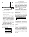
• When the unit is heating, the temperature of the return
air entering the unit must be between 50° F and 100°
F.
GROUND LEVEL INSTALLATIONS ONLY:
• When the unit is installed on the ground adjacent to
the building, a level concrete (or equal) base is
recommended. Prepare a base that is 3” larger than
the package unit footprint and a minimum of 3” thick.
• The base should also be located where no runoff of
water from higher ground can collect in the unit.
ROOF TOP INSTALLATIONS ONLY:
• To avoid possible property damage or personal injury,
the roof must have sufficient structural strength to carry
the weight of the unit(s) and snow or water loads as
required by local codes. Consult a structural engineer
to determine the weight capabilities of the roof.
• The unit may be installed directly on wood floors or
on Class A, Class B, or Class C roof covering material.
• To avoid possible personal injury, a safe, flat surface
for service personnel should be provided.
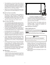
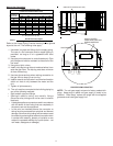
• As indicated on the unit data plate, a minimum
clearance of 36” to any combustible material is
required on the furnace access side of the unit. All
combustible materials must be kept out of this area.
• This 36” clearance must also be maintained to insure
proper combustion air and flue gas flow. The
combustion air intake and furnace flue discharge must
not be blocked for any reason, including blockage by
snow.
• Adequate clearances from the furnace flue discharge
to any adjacent public walkways, adjacent buildings,
building openings or openable windows must be
maintained in accordance with the latest edition of
the National Fuel Gas Code (ANSI Z223.1)
• Minimum horizontal clearance of 48” from the furnace
flue discharge to any electric meters, gas meters,
regulators and relief equipment is required.
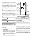
UNIT PRECAUTIONS
• Do not stand or walk on the unit.
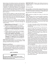
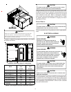
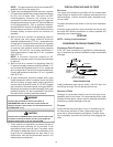
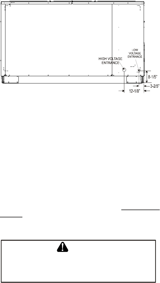
• Except for holes in the wiring entrances (see Figure
below), do not drill holes anywhere in panels or in
the base frame of the unit. Unit access panels
provide structural support.
ELECTRICAL ENTRANCE LOCATIONS
• Do not remove any access panels until unit has been
installed on roof curb or field supplied structure.
• Do not roll unit across finished roof without prior
approval of owner or architect.
• Do not skid or slide on any surface as this may
damage unit base. The unit must be stored on a
flat, level surface. Protect the condenser coil
because it is easily damaged.
ROOF CURB INSTALLATIONS ONLY:
Before installing this unit...
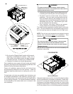
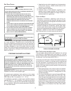
IMPORTANT NOTE: This unit has been equipped with a ship-
ping brace under the compressor section that MUST BE RE-
MOVED before installing the unit on a roof curb.
Please follow the instructions below to remove brace.
W
HEN
UNIT
IS
SUSPENDED
,
BOARDS
AND
SHIPPING
BRACE
WILL
DROP
WHEN
SCREWS
ARE
REMO VE D
.T
O
PREVENT
PERSONAL
INJURY
,STANDCLEAR .
R
EMOVE
FORK
HOLE
BRACKETS
,
BOARDS
AND
SHIPPING
BRACE
FROM
BOTTOM
OF
UNIT
BEFORE
PLACING
UNIT
ONTO
CURB
.
CAUTION
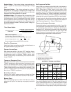
1. Remove wooden struts and shipping brace per
installation instructions. The struts are located in the
fork holes and are used to protect the unit from
damage while lifting with forks. The shipping brace
is located under the unit (under compressor). Also
remove the fork hole brackets as shown in the
following figure.
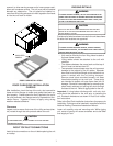
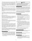
2. Locate and remove the end brackets as shown in the
following figure.