


10
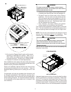
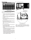
ELECTRICAL ENTRANCE LOCATIONS
Unit is equipped with a Low Voltage Terminal Block and has
Single Point wiring to the contactor.
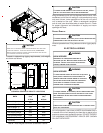
LOW VOLTAGE CONTROL WIRING
1. A 24V thermostat must be installed for unit operation.
It may be purchased with the unit or field -supplied.
Thermostats may be programmable or
electromechanical as required.
2. Locate thermostat or remote sensor in the conditioned
space where it will sense average temperature. Do
not locate the device where it may be directly exposed
to supply air, sunlight or other sources of heat. Follow
installation instructions packaged with the thermostat.
3. Use #18 AWG wire for 24V control wiring runs not
exceeding 75 feet. Use #16 AWG wire for 24V control
wiring runs not exceeding 125 feet. Use #14 AWG
wire for 24V control wiring runs not exceeding 200
feet. Low voltage wiring may be National Electrical
Code (NEC) Class 2 where permitted by local codes.
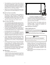
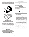
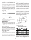
4. Route thermostat wires from sub-base terminals to
the unit. Control wiring should enter through the duct
panel (dimple marks entrance location). Connect
thermostat and any accessory wiring to low voltage
terminal block TB1 in the main control box.
NOTE: Field-supplied conduit may need to be installed
depending on unit/curb configuration. Use #18 AWG solid
conductor wire whenever connecting thermostat wires to
terminals on sub-base. DO NOT use larger than #18 AWG
wire. A transition to #18 AWG wire may be required before
entering thermostat sub-base.
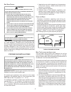
LEAD THERMOSTAT
Red R (24V)
Green G (Fan)
Yellow Y1 (High Cool)
Purple Y2 (Low Cool)
Blue Common (if req'd)
White W1 (Heat)
Brown W2 (High Heat)
CPG240 (GAS HEAT)
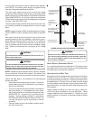
GAS SUPPLY PIPING
T
O
PREVENT
PERSONAL
INJURY
OR
DEATH
DUE
TO
IMPROPER
INSTALLATION
,
ADJUSTMENT
,
ALTERATION
,
SERVICE
OR
MAINTENANCE
,
REFER
TO
THIS
MANUAL
.F
OR
ADDITIONAL
ASSISTANCE
OR
INFOR MATION
,
CONSULT
A
QUALIFIED
INSTALLER
,
SERVICE
AGENCY
OR
THE
GAS
SUPPLIER
.
WARNING
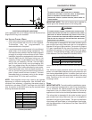
IMPORTANT NOTE: This unit is factory set to operate on
natural gas at the altitudes shown on the rating plate.
T
O
PREVEN T
PROPERTY
DAMAGE
,
PERSONAL
INJURY
OR
DEATH
WHEN
EITHER
USING
PROPANE
GAS
ALONE
OR
AT
HIGHER
ALTITUDES
,
OBTAIN
AND
INSTALL
THE
PROPER
CONVERSION
KIT
(
S
).F
AILURE
TO
DO
SO
CAN
RESULT
IN
UNSATISFACTORY
OPERATION
AND
/
OR
EQU IPMENT
DAMAGE
.
H
IGH
ALTITUD E
KITS
ARE
FOR
U.S.I
NSTALLATIONS
ONLY
AND
ARE
NOT
APPROVED
FOR
USE
IN
C
ANADA
.
WARNING
The rating plate is stamped with the model number, type of
gas and gas input rating. Make sure the unit is equipped to
operate on the type of gas available. Conversion to propane
(LP) gas is permitted with the use of the factory authorized
conversion kit (see the unit Technical Manual for the appro-
priate kit). For High Altitude derates, refer to the latest edition
of the National Fuel Gas Code NFPA 54/ANSI Z223.1.
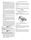
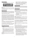
NATURAL
Min. 5.0" W.C., Max. 10.0" W.C.
PROPANE
Min. 11.0" W.C., Max. 14.0" W.C.
INLET GAS PRESSURE
Inlet Gas Pressure Must Not Exceed the Maximum Value Shown in Table
Above.
The minimum supply pressure should not vary from that
shown in the table above because this could prevent the unit
from having dependable ignition. In addition, gas input to the
burners must not exceed the rated input shown on the rating
plate. Overfiring of the unit could result in premature heat
exchanger failure.
PIPING
IMPORTANT NOTE: To avoid possible unsatisfactory opera-
tion or equipment damage due to under firing of equipment,
do not undersize the natural/propane gas piping from the
meter/tank to the unit. When sizing a trunk line, include all
appliances on that line that could be operated simultaneously.
The rating plate is stamped with the model number, type of
gas and gas input rating. Make sure the unit is equipped to
operate on the type of gas available. The gas line installation
must comply with local codes, or in the absence of local codes,
with the latest edition of the National Fuel Gas Code NFPA
54/ANSI Z223.1.