


11
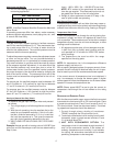
Natural Gas Connection
Len
g
th of
Pipe in Feet
1/2 3/4
1
1 1/4 1 1/2
10 132 278 520 1050 1600
20 92 190 350 730 1100
30 73 152 285 590 980
40 63 130 245 500 760
50 56 115 215 440 670
60 50 105 195 400 610
70 46 96 180 370 560
80 43 90 170 350 530
90 40 84 160 320 490
100 38 79 150 305 460
Pressure = .50 PSIG or less and Pressure Drop of 0.3" W.C. (Based
on 0.60 S
p
ecific Gravit
y
Gas
)
Natural Gas Capacity of Pipe
in Cubic Feet of Gas Per Hour
(
CFH
)
Nominal Black Pipe Size (inches)
BTUH Furnace Input
Heatin
g
Value of Gas
(
BTU/Cubic Foot
)
CFH =
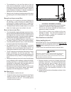
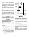
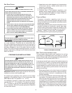
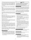
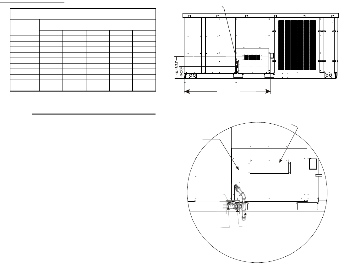
Refer to the Proper Piping Practice drawing for the general
layout at the unit. The following rules apply:
1. Use black iron pipe and fittings for the supply piping.
The use of a flex connector and/or copper piping is
permitted as long as it is in agreement with local
codes.
2. Use pipe joint compound on male threads only. Pipe
joint compound must be resistant to the action of the
fuel used.
3. Use ground joint unions.
4. Install a drip leg to trap dirt and moisture before it can
enter the gas valve. The drip leg must be a minimum
of three inches long.
5. Use two pipe wrenches when making connection to
the gas valve to keep it from turning.
6. Install a manual shut-off valve in a convenient location
(within six feet of unit) between the meter and the
unit.
7. Tighten all joints securely.
8. The unit must be connected to the building piping by
one of the following methods:
• Rigid metallic pipe and fittings
• Semirigid metallic tubing and metallic fittings
(Aluminum alloy tubing must not be used in exterior
locations)
• Listed gas appliance connectors used in accordance
with the terms of their listing that are completely in
the same room as the equipment
• In the prior two methods above the connector or
tubing must be protected from physical and thermal
damage. Aluminum alloy tubing and connectors must
be coated to protect against external corrosion when
in contact with masonry, plaster or insulation or are
subject to repeated wettings by liquids (water - not
rain water, detergents or sewage).
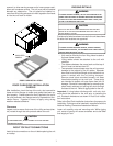
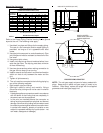
46-1/10”
GAS INLET LOCATION (3/4” NPT)
46-1/10”46-1/10”
74-11/12”
HOOD LOCATED
INSIDE HEAT SECTION
DURING SHIPPING
DOOR
PROVIDE
CLEARANCE
FOR REMOVAL OF
ACCESS PANELS
DRIP LEG
GROUND
JOINT
UNION
MANUAL
SHUT OFF
VALVE
PROPER PIPING PRACTICE
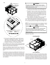
NOTE: The unit gas supply entrance is factory sealed with
plugs. Keep plugs in place until gas supply is ready to be
installed. Once ready, replace the plugs with the supplied
grommets and install gas supply line.