


17
With Power And Gas On:
2. Put unit into heating cycle and turn on all other gas
consuming appliances.
NATURAL
Min. 5.0" W.C., Max. 10.0" W.C.
PROPANE
Min. 11.0" W.C., Max. 14.0" W.C.
INLET GAS PRESSURE
NOTE: Inlet Gas Pressure Must Not Exceed the Maximum
Value Shown.
If operating pressures differ from above, make necessary
pressure regulator adjustments, check piping size, etc., and/
or consult with local utility.
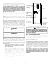
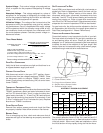
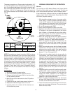
Manifold Pressure Check
The gas valve has a tapped opening to facilitate measure-
ment of the manifold pressure. A “U” Tube manometer hav-
ing a scale range from 0 to 12 inches of water should be
used for this measurement. The manifold pressure must be
measured with the burners operating.
To adjust the pressure regulator, remove the adjustment screw
or cover on the gas valve. Turn out (counterclockwise) to
decrease pressure, turn in (clockwise) to increase pressure.
Only small variations in gas flow should be made by means
of the pressure regulator adjustment. In no case should the
final manifold pressure vary more than plus or minus 0.3
inches water column from the specified nominal pressure.
Any major changes in flow should be made by changing the
size of the burner orifices. The measured input rate to the
furnace must not exceed the rating specified on the unit rat-
ing plate.
For natural gas, the manifold pressure must be between 3.2
and 3.8 inches w.c. (3.5 nominal) for high fire and between
1.7 and 2.3 inches w.c. (2.0 nominal) for low fire.
For propane gas, the manifold pressure must be between
9.7 and 10.3 inches w.c. (10.0 nominal) for high fire and be-
tween 6.7 and 7.3 inches w.c. (7.0 nominal) for low fire.
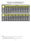
Gas Input (Natural Gas Only) Check
To measure the gas input use a gas meter and proceed
as follows:
1. Turn off gas supply to all other appliances except the
unit.
2. With the unit operating, time the smallest dial on the
meter for one complete revolution. If this is a 2 cubic
foot dial, divide the seconds by 2; if it is a 1 cubic foot
dial, use the seconds as is. This gives the seconds
per cubic foot of gas being delivered to the unit.
3. INPUT=GAS HTG VALUE x 3600 / SEC. PER CUBIC
FOOT
Example: Natural gas with a heating value of 1000 BTU per
cubic foot and 34 seconds per cubic foot as determined by
Step 2, then:
Input = 1000 x 3600 / 34 = 106,000 BTU per Hour.
NOTE: BTU content of the gas should be obtained
from the gas supplier. This measured input must not
be greater than shown on the unit rating plate.
4. Relight all other appliances turned off in step 1. Be
sure all pilot burners are operating.
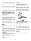
Main Burner Flame Check
Flames should be stable, soft and blue (dust may cause or-
ange tips but they must not be yellow) and extending directly
outward from the burner without curling, floating or lifting off.
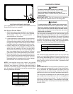
Temperature Rise Check
Check the temperature rise through the unit by placing ther-
mometers in supply and return air registers as close to the
unit as possible. Thermometers must not be able to sample
temperature directly from the unit heat exchangers, or false
readings could be obtained.
1. All registers must be open; all duct dampers must be
in their final (fully or partially open) position and the
unit operated for 15 minutes on HIGH FIRE before
taking readings.
2. The temperature rise must be within the range
specified on the rating plate.
NOTE: Air temperature rise is the temperature difference
between supply and return air.
With a properly designed system, the proper amount of tem-
perature rise will normally be obtained when the unit is oper-
ated at rated input with the recommended blower speed.
If the correct amount of temperature rise is not obtained, it
may be necessary to change the blower speed. A higher
blower speed will lower the temperature rise. A slower blower
speed will increase the temperature rise.
NOTE: Blower speed MUST be set to give the correct air
temperature rise through the unit as marked on the rating
plate.
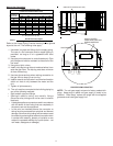
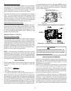
REFRIGERATION SEQUENCE CHECK
With the disconnect switch open, remove the field connected
thermostat wire from terminal R on TB1 terminal block. Place
a jumper across terminals R and G, and across R and Y on
TB1 terminal block. Close the disconnect switch. The follow-
ing operational sequence should be observed.
1. Current through primary winding of transformer
TRANS1 energizes the 24-volt control circuit.
2. To simulate a mechanical call for cooling from the wall
thermostat, place a jumper across terminals R and
Y1 of terminal block TB1.
3. UNIT WITH ECONOMIZER OPTION: The
compressor circuit is interlocked through terminals 3
and 4 of the economizer module. If the outdoor air
enthalpy (temperature and humidity) is not suitable
for cooling, the economizer terminals will be closed
permitting compressor to be energized.