


23
Disposable return air filters are supplied with this unit. See
the unit Specification Sheet or Technical Manual for the cor-
rect size and part number. To remove the filters, remove the
filter access panel on return side of the unit.
CABINET FINISH MAINTENANCE
Use a fine grade automotive wax on the cabinet finish to
maintain the finish’s original high luster. This is especially
important in installations with extended periods of direct sun-
light.
CLEAN OUTSIDE COIL (QUALIFIED SERVICER ONLY)
The coil with the outside air flowing over it should be inspected
annually and cleaned as frequently as necessary to keep the
finned areas free of lint, hair and debris.
CONDENSER, EVAPORATOR, AND INDUCED DRAFT MOTORS
Bearings on the air circulating blower motor, condenser mo-
tor and the combustion fan motor are permanently lubricated.
No additional oiling is required.
FLAME SENSOR (QUALIFIED SERVICER ONLY)
A drop in the flame current can be caused by a nearly invis-
ible coating on the flame sensor. This coating, created by the
fuel or combustion air supply, can be removed by carefully
cleaning the flame sensor with steel wool.
NOTE: After cleaning, the microamp signal should be stable
and in the range of 4 - 6 microamps DC.
FLUE PASSAGES (QUALIFIED SERVICER ONLY)
At the start of each heating season, inspect and, if neces-
sary, clean the unit flue passage.
LUBRICATION
The fan shaft bearings, the 1 to 2 HP supply fan motors the
condenser fan motors and compressors are permanently lu-
bricated.
INSPECTION & CLEANING
All flue product carrying areas of the furnace, its vent sys-
tem, and main burners should be examined by a qualified
service agency before the start of each heating season. This
examination is necessary for continued safe operation. Par-
ticular attention should be given to deterioration from corro-
sion or other sources. This examination is accomplished in
the following manner.
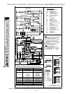
1. Disconnect power to the unit and remove furnace
section access panel.
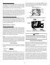
2. Remove burner assembly:
a. Disconnect the three wires from the gas valve after
noting which wires are connected to each terminal.
b. Disconnect wires from the flame rod and ignition
electrode.
c. Disconnect the gas piping at the union.
d. The entire burner assembly can now be removed
from the unit.
NOTE: Use all screws that were removed; they are
necessary for safe and proper operation of the unit.
3. Inspect and periodically clean the vent outlet (bird
screen) on the access panel.
NOTE: Periodic observation of the flame and a log of C0
2
measurements are recommended. This will aid in determining
whether the furnace is operating efficiently or if the furnace
requires cleaning.
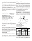
Flames should be stable, soft and blue (dust may cause or-
ange tips but must not be yellow). The flames must extend
directly outward from the burner without curling, floating or
lifting off.
BURNER FLAME
T
O
AVOID
PERSONAL
INJURY
OR
DEATH
DUE
TO
ELECTRIC
SHOCK
,
DO
NOT
REMOVE
ANY
INTERNAL
COMPARTMENT
COVERS
OR
ATTEMPT
ANY
ADJUSTMENT
.C
ONTACT
A
QUALIFIED
SERVICER
AT
ONCE
IF
AN
ABNORM AL
FLAME
SHOULD
DEVELOP
.
WARNING
At least once a year, prior to or during the heating season,
make a visual check of the burner flames.
NOTE: This will involve removing and reinstalling the heat
exchanger door on the unit, which is held by two screws. If
you are uncertain about your ability to do this, contact a
qualified servicer.
If a strong wind is blowing, it may alter the airflow pattern
within the unit enough that an inspection of the burner flames
is not possible.
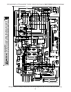
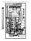
FUNCTIONAL PARTS
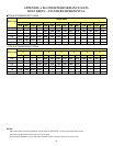
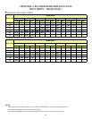
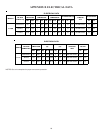
Refer to the unit Parts Catalog for a list of functional parts.
Parts are available from your distributor.