


12
GAS PIPING CHECKS
T
O
PREVENT
PROPERTY
DAMAGE
OR
PERSONAL
INJURY
DUE
TO
FIRE
,
THE
FOLLOWING
INSTRUCTIONS
MUST
BE
PERFORMED
REGARDING
GAS
CONNECTIONS
AND
PRESSURE
TESTING
:
•T
HE
UNIT
AND
ITS
GAS
CONNECTIONS
MUST
BE
LEAK
TESTED
BEFORE
PLACING
IN
OPERATION
.B
ECAU SE
OF
THE
DANGER
OF
EXPLOSION
OR
FIRE
,
NEVER
USE
A
MATCH
OR
OPEN
FLAME
TO
TEST
FOR
LEA KS
.N
EVER
EXC EED
SPECIFIED
PRESSURES
FOR
TESTING
.
H
IGHER
PRESSURE
MAY
DAMAGE
GAS
VALVE
AND
CAUSE
OVERFIRING
WHICH
MAY
RESULT
IN
PREMATURE
HEAT
EXCH ANGE
FAILURE
.
•T
HIS
UNIT
AND
ITS
SHUT
‐
OFF
VALVE
MUST
BE
DISCONNECTED
FROM
THE
GAS
SUPPLY
DURING
ANY
PRESSURE
TESTING
OF
THAT
SYSTEM
AT
TEST
PRESSURES
IN
EXC ESS
OF
1/2PSIG(3.4 8
K
P
A
).
•T
HIS
UNIT
MUST
BE
ISOLATED
FROM
THE
GAS
SUPPLY
SYSTEM
BY
CLOSING
ITS
MANUAL
SHUT
‐
OFF
VALVE
DURING
ANY
PRESSURE
TESTING
OF
THE
GAS
SUPPLY
PIPING
SYSTEM
AT
TEST
PRESSURES
EQUAL
TO
OR
LESS
THAN
1/2PSIG(3.4 8
K
P
A
).
CAUTION
T
O
AVOID
PROPERTY
DAMAGE
OR
PERSONAL
INJURY
,
BE
SURE
THERE
IS
IN
THE
VICINITY
DURING
AIR
BLEED ING
.
NO
OPEN
FLAME
WARNING
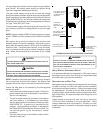
There will be air in the gas supply line after testing for leaks
on a new installation. Therefore, the air must be bled from
the line by loosening the ground joint union until pure gas is
expelled. Tighten union and wait for five minutes until all gas
has been dissipated in the air. Be certain there is no open
flame in the vicinity during air bleeding procedure. The unit is
placed in operation by closing the main electrical disconnect
switch for the unit.
PROPANE GAS INSTALLATIONS
T
O
AVOID
PROPERTY
DAMAGE
,
PERSONAL
INJURY
OR
DEATH
DUE
TO
FIRE
OR
EXPLOSION
CAUSED
BY
A
PROPANE
GAS
LEA K
,
INSTALL
A
GAS
DETECTING
WARNING
DEVICE
.S
INCE
RUST
CAN
REDUCE
THE
LEVEL
OF
ODORANT
IN
PROPANE
GAS
,
A
GAS
DETECTING
WARNING
DEVICE
IS
THE
ONLY
RELIABLE
WAY
TO
DETECT
A
PROPANE
GAS
LEA K
.C
ONTACT
A
LOCAL
PROPANE
GAS
SUPPLIER
ABOUT
INSTALLING
A
GAS
DETECTING
WARNING
DEVICE
.
WARNING
IMPORTANT NOTE: Propane gas conversion kits must be
installed to convert units to propane gas.
All propane gas equipment must conform to the safety
standards of the National Board of Fire Underwriters (See
NBFU Manual 58). Line pressure 11.3 - 14” w.c.
For satisfactory operation, propane gas manifold pressure
must be within 9.7 - 10.3 inches w.c. for high fire and within
6.7 - 7.3 inches w.c. low fire at the manifold with all gas appli-
ances in operation. Maintaining proper gas pressure depends
on three main factors:
1. Vaporization rate, which depends on (a) temperature
of the liquid, and (b) wetted surface area of the
container or containers.
2. Proper pressure regulation.
3. Pressure drop in lines between regulators, and
between second stage regulator and the appliance.
Pipe size required will depend on length of pipe run
and total load of all appliances.
TANKS AND PIPING
Complete information regarding tank sizing for
vaporization, recommended regulator settings and pipe
sizing is available from most regulator manufacturers and
propane gas suppliers.
Since propane gas will quickly dissolve white lead or most
standard commercial compounds, special pipe dope
must be used. Shellac base compounds resistant to the
actions of liquefied petroleum gases such as Gasolac
®
,
Stalactic
®
, Clyde’s
®
or John Crane
®
are satisfactory.
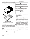
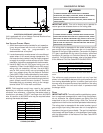
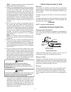
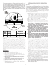
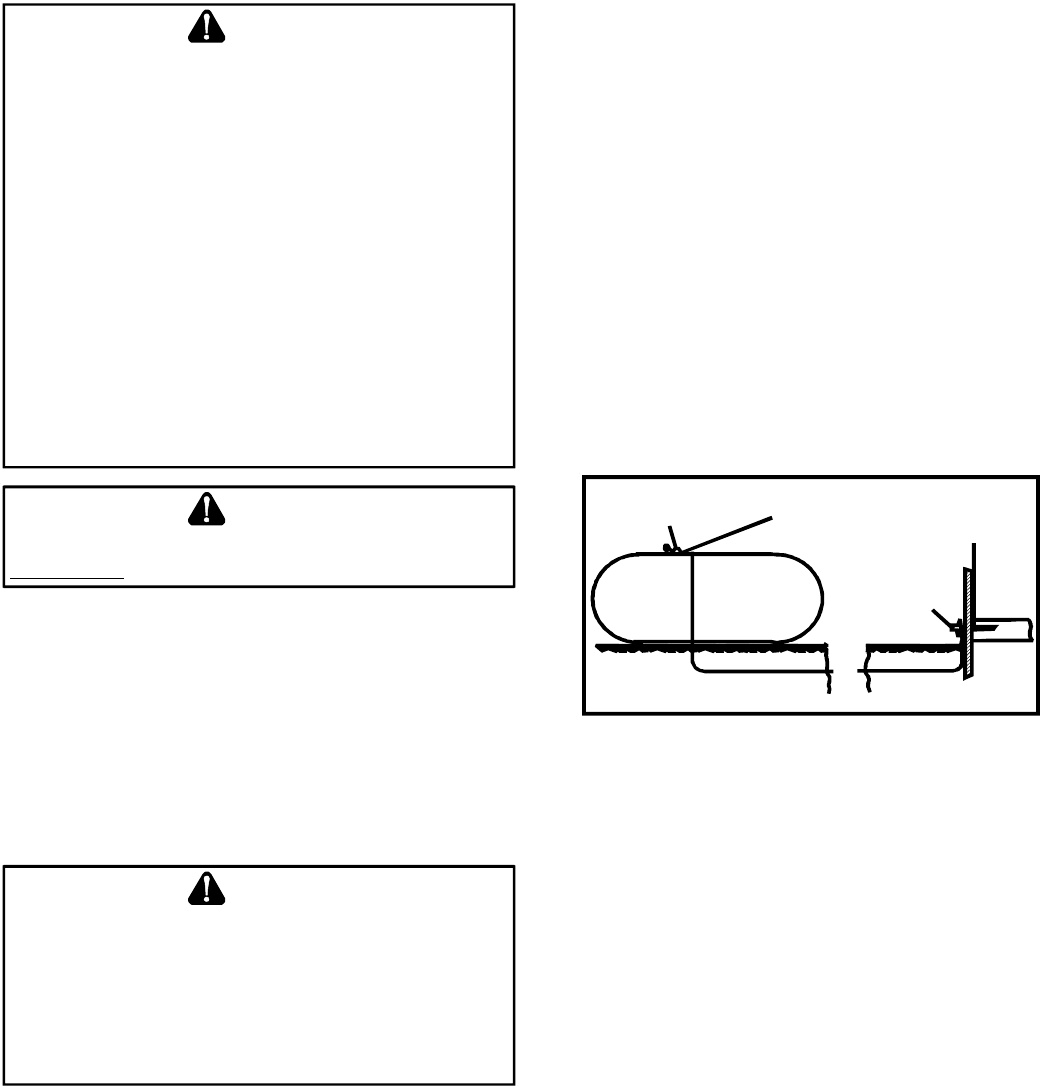
See following figure for typical propane gas piping.
200 PSIG
Maximum
5 to 15 PSIG
(20 PSIG Max.)
Continuous
11" W.C.
Second Stage
Regulator
First Stage
Regulator
TYPICAL PROPANE GAS PIPING
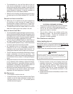
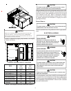
ROOF TOP LOCATION AND INSTALLATION
The gas supply piping location and installation for roof top
units must be in accordance with local codes or, in the ab-
sence of locals codes, with ordinances of the latest edition of
the National Fuel Gas Code (ANSI Z223.1).
A manual gas shutoff valve must be field installed external to
the roof top unit. In addition, a drip leg must be installed near
the inlet connection. A ground joint union connection is re-
quired between the external shutoff valve and the unit con-
nection to the gas valve to permit removal of the burner as-
sembly for servicing.
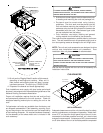
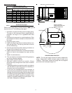
1. Route gas piping to unit so that it does not interfere
with the removal of access panels. Support and align
piping to prevent strains or misalignment of the
manifold assembly.
2. All units are furnished with standard female NPT pipe
connections. Connection pipe size is 3/4" NPT. The
size of the gas supply piping to the unit must be based
on length of run, number of units on the system, gas
characteristics, BTU requirement and available supply
pressure. All piping must be done in accordance with
local codes or, in the absence of local codes, with the
latest edition of the National Fuel Gas Code (ANSI
Z223.1).