


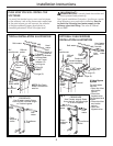
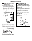
Installation Instructions
8
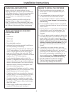
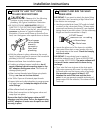
CONNECT AND RUN THE VALVE
DRAIN HOSE
(CONT.)
• Elevating the drain hose may cause back
pressure that could reduce the brine draw during
recharge. If raising the drain line overhead is
required to get to the drain point, measure the
inlet water pressure to the softener first. For inlet
pressures between 20 and 50 psi, do not raise
higher than 8′ above the floor. For inlet pressure
above 50 psi, the drain line may be raised to a
maximum height of 14′.
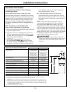
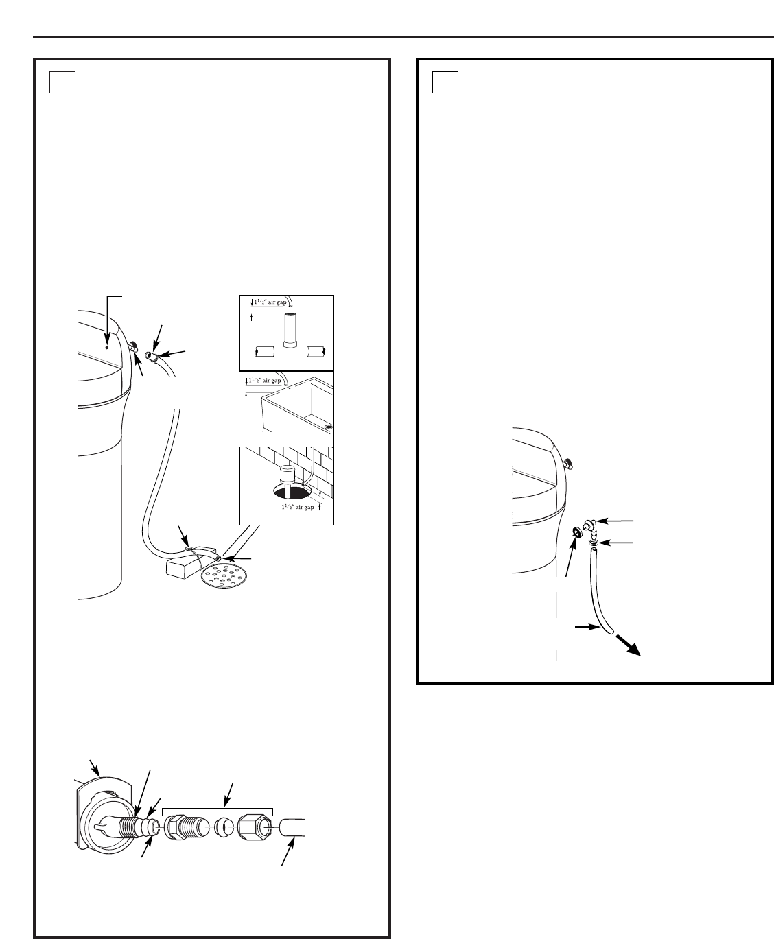
CONNECTING A RIGID VALVE DRAIN TUBE
To adapt a copper drain tube to the softener, buy a
compression fitting (1/4 NPT x 1/2″ O.D. tube) and
needed tubing from your local hardware store.
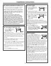
5
Drain fitting
on valve
Valve drain hose
FLOOR DRAIN
Tie or
wire
hose in
place
1
1
⁄2″ air gap
LAUNDRY TUB
SUMP
Clamp
STANDPIPE
Blue indicator
light
Clip
1/4″ NPT
thread
1/2″ outside
diameter copper
tube (not provided)
Compression fitting
1/4 NPT x 1/2″ O.D.
tube (not provided)
Cut barbs from valve
drain elbow (pull clip
and remove drain valve
elbow from valve)
Barbs
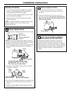
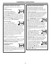
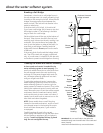
INSTALL THE BRINE TANK
OVERFLOW FITTINGS AND HOSE
• Insert the rubber grommet into the 3/4″ diameter
hole in the brine tank sidewall as shown.
• Push the end of the hose adapter elbow into the
grommet as shown.
• Attach a length of hose (use remaining hose from
Step 5) to the hose adapter elbow. Use a hose
clamp to hold it in place.
• Locate the other end of the hose at the drain
point. DO NOT ELEVATE this hose higher than the
elbow on the brine tank.
IMPORTANT: DO NOT TEE OVERFLOW HOSE TO
VALVE DRAIN HOSE.
NOTE: This drain is for safety only. If the cabinet
(brine tank) should over-fill with water, the excess is
carried to the drain.
6
To acceptable
drain
Overflow
drain hose
Hose
clamp
Grommet
Do not connect
to valve drain
hose.
Hose
adapter