


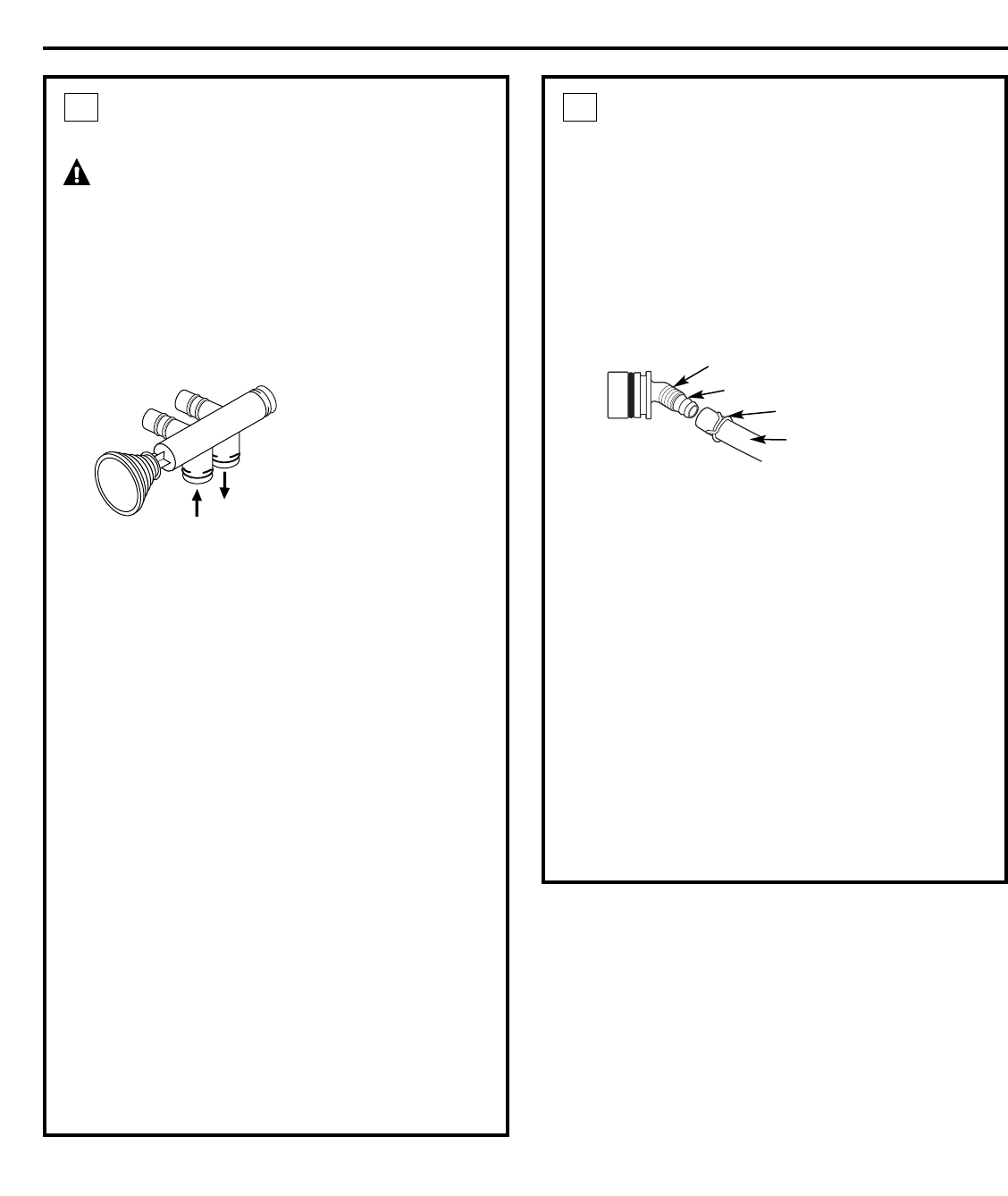
PLUMB “IN” AND “OUT” PIPES
TO AND FROM SOFTENER
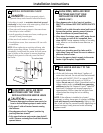
CAUTION: Observe all of the following
cautions as you connect inlet and outlet
plumbing. See Typical Installation Illustration.
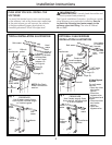
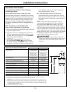
• BE SURE INCOMING HARD WATER SUPPLY IS
DIRECTED TO THE SOFTENER VALVE INLET PORT.
If house water flow is from the left, use a plumbing
crossover as shown in Typical Installation
Illustration. If house water flows up from the floor
level, turn the bypass valve upside down as shown.
• With the softener in place, determine the correct
length of piping required to connect the household
plumbing to the NPT male adapter.
• Remove softener from installation space.
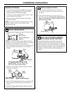
• If making a soldered copper installation, do all
sweat soldering before connecting pipes to the
NPT adapters and bypass valve. Torch heat will
damage plastic parts.
• When turning threaded pipe fittings onto plastic
fittings, use care not to cross-thread.
• Use Teflon Tape on all external pipe threads.
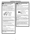
• Support inlet and outlet plumbing in some manner
(use pipe hangers) to keep the weight off of the
valve fittings.
• Slide softener back into position.
• Make final connections to the bypass valve and
snap clips into place.
Be sure the clips for the bypass valve and NPT
adapters snap into place. Pull on the bypass valve
and NPT adapters to make sure the parts are held
securely in place.
4
Installation Instructions
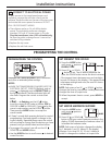
7
IN
OUT
Turn bypass
valve upside
down to
connect to
floor level
plumbing
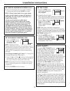
CONNECT AND RUN THE VALVE
DRAIN HOSE
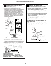
IMPORTANT: If you want to attach the drain fitting
to a rigid tube, see Connecting a Rigid Valve Drain
Tube section on next page.
• Use the provided drain hose (20′ length included)
to attach to the valve drain fitting. To keep water
pressure from blowing the hose off, use supplied
spring clamp to secure in place. Cut the necessary
length and use the remainder in Step 6.
• Locate the other end of the hose at a suitable
drain point (floor drain, sump, laundry tub, etc.)
that terminates at the sewer. Check and comply
with local codes.
IMPORTANT: If more drain hose is needed, it
should be ordered from GE Parts at 800.626.2002,
part number WS07X10004. The water softener will
not work if water cannot exit this hose during
recharge.
• Tie or wire the hose in place at the drain point.
High water pressure will cause it to whip during
the back-wash and fast rinse cycles of recharge.
Also provide an air gap of at least 1-1/2″
between the end of the hose and the drain
point. An air gap prevents possible siphoning of
sewer water into the softener, if the sewer should
“back-up.”
5
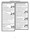
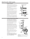
Barbs for 3/8
″
I.D. tubing
Hose clamp
1/4
″
NPT thread
Drain hose