


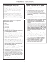
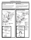
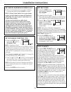
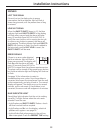
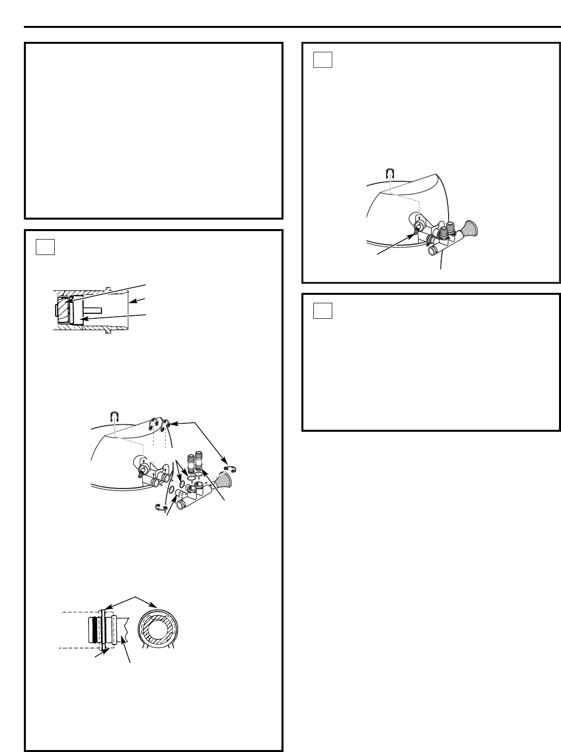
INSTALL DRAIN FITTING
• Push the drain fitting (lubricate o-ring seals
with silicone grease) into the part of the valve
as shown.
• Snap the large plastic clip in place, from the
top down as shown. Be sure the clip snaps into
place. Pull on the drain fitting to make sure it is
held securely in place.
2
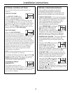
INSTALL BYPASS VALVE
• Remove plastic shipping plug and wire from valve
outlet.
• Push the bypass valve (lubricate o-ring seals with
silicone grease) into both ports of the valve as
shown.
• Snap the 2 large plastic clips in place, from the
top down, as shown.
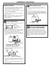
• Push the NPT adapters (lubricate o-ring seals with
silicone grease) into both ports of the valve as
shown
• Snap the 2 large plastic clips in place, from the
side, as shown.
1
Valve body
inlet or outlet
Bypass valve
(push all the way in)
Clip
END
VIEW
SIDE
VIEW
Installation Instructions
6
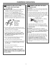
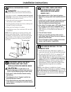
BEFORE YOU BEGIN
• Turn off the gas or electric supply to the water
heater, in the possibility that the water heater
may be drained while draining pipes.
• Turn off the water supply to pipes to be cut and
drain the house water pipes.
• Open both hot and cold faucets at the lowest
location possible.
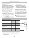
NOTE: For easier installation, remove the top cover.
Release 2 clips at rear of cover. Rotate cover
forward and lift up.
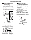
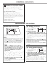
Turbine
Valve outlet
Turbine shaft and
support
NOTE: Be sure the turbine and support are firmly
in place in the valve outlet. Blow into the valve port
and observe the turbine for free rotation.
Clips
O-rings
O-ring seal goes into the outer
groove only. The clip snaps into
the inner groove (see below).
NPT adapter
Drain fitting
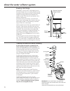
MOVE THE SOFTENER ASSEMBLY
INTO INSTALLATION POSITION
Before sliding softener in position, be sure the
installation surface is level and smooth. Sharp
objects under the tank may puncture it. If needed,
place the tank on a section of 3/4″ thick (minimum)
plywood. Then, place shims under the plywood as
needed to level the softener. Slide softener into
position.
3