


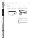
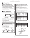
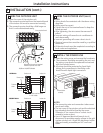
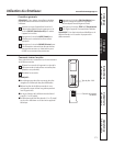
WIRE THE OUTDOOR UNIT
1. Open the cover of the outdoor unit.
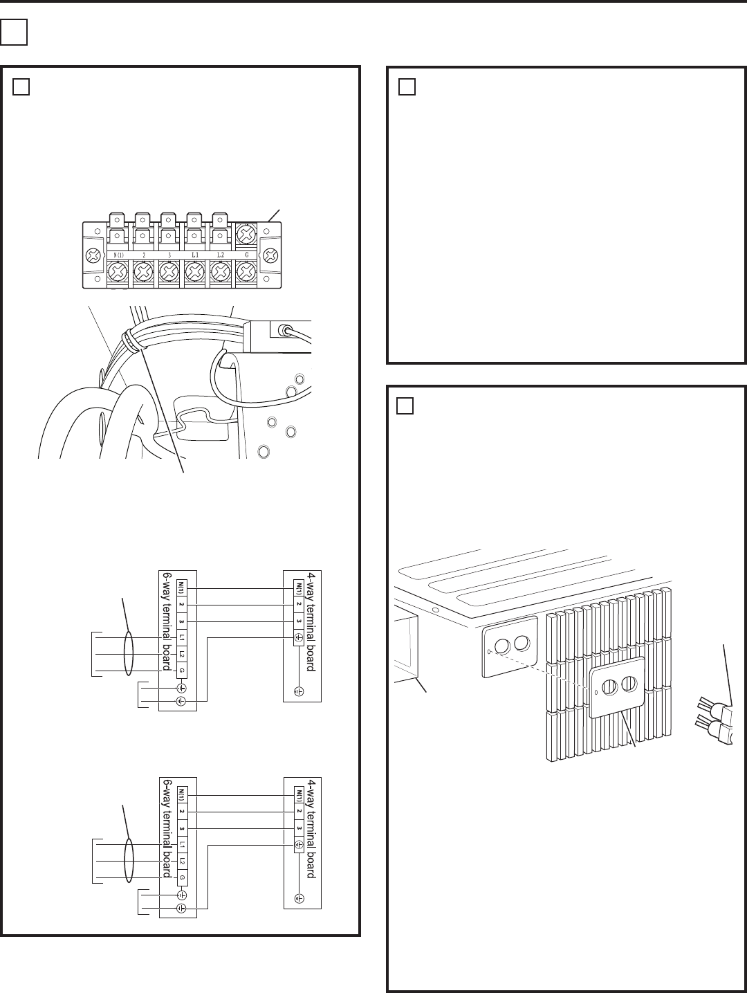
2. The connecting wire lead from the terminal board
of the indoor unit must be connected correctly.
3. The connecting wire should be a little longer so
that it can be maintained easily.
Installation Instructions
14
8
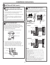
WIRE THE OUTDOOR UNIT (cont.)
NOTES:
• Wiring should be consistent with the above wiring
diagrams.
• Wiring must be correct.
• Tighten the nut of the terminal board to keep the
board secured.
• After tightening, the wire cannot be removed if
pulled.
• Incorrect wiring will cause the air conditioner to
work abnormally.
• Incorrect grounding will cause a short circuit.
• Electrical connections must be made by a qualified
electrician.
• All electrical work must be completed according to
local codes and regulations.
8
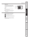
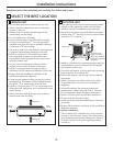
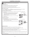
INSTALL THE POWER LINE
1. Open the wiring cover and remove the knockouts.
2. The connector should be secured by the nut, and
the wiring cover should be replaced and secured
with the included screw.
3. All wiring should be protected by liquid-tight
tubing, and connections to the wiring cover
should be with liquid-tight connectors.
NOTES:
• The connecting wire and connection tube cannot
touch each other.
• The top cover of the outdoor unit and the electrical
box assembly should be fixed by the screw.
Otherwise, it can cause a fire or a short circuit
caused by water or dust.
• Use a UL-approved electrical branch circuit
disconnect for providing supply voltage to the split
system outdoor unit. Locate the disconnect within
sight and readily accessible per NEC and local
codes.
Connector
Electrical box
assembly
Wiring cover
6-way terminal board
Wrap electrical cords with attached
metal tie to provide strain relief.
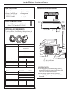
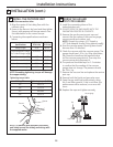
10,000 and 14,000 BTU Models
9
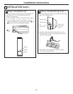
Indoor unit
*L1 will be used for neutral
in 115V models.
Outdoor unit
To branch
circuit
Ground
Power supply
115V Models
Indoor unit
Outdoor unit
To branch
circuit
Ground
Power supply
230/208V Models
INSTALLATION (cont.)
2