


Installation Instructions
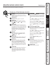
CONNECT ELECTRICAL WIRING
BETWEEN INDOOR AND OUTDOOR
UNITS
• All wiring should be rated appropriately for the
current value listed on the rating plate.
• The power supply should accommodate the rated
voltage.
• Wiring must be done by a qualified electrician
according to local codes, regulations and this
manual.
• All wiring connections should be tightened securely.
5
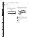
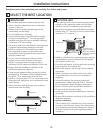
WIRE THE INDOOR UNIT
NOTE:
Use UL-approved electrical branch circuit
disconnect for providing supply voltage to split system
indoor and outdoor units. Locate disconnect within sight
and readily accessible per NEC and local codes
.
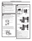
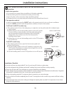
1. Open the front access panel.
2. Remove the cover plate of the electrical box.
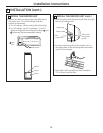
3. On the back of the indoor unit, remove the
conduit connecting cover. Using the fixing nut,
connect the conduit to the connecting cover.
Route the wire leads through the unit to the
electrical box area. Reinstall the connecting cover.
6
Cover plate
Access panel
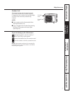
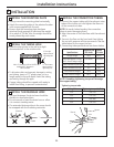
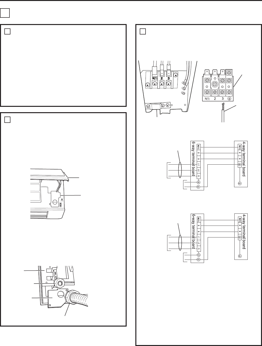
WIRE THE INDOOR UNIT (cont.)
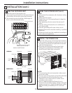
NOTE: Wiring must be done by a qualified electrician
according to the local codes and regulations and
this manual. The connecting wire should be correctly
connected to the circuit interface.
NOTES:
• Wiring should be consistent with the wiring
diagrams above.
• Tighten the nut of the terminal board to keep
the board secured.
• After tightening, the wire cannot be removed
if pulled.
• Incorrect wiring will cause the air conditioner
to work abnormally.
• Incorrect grounding will cause a short circuit.
4. Replace the cover plate over the electrical box
and lower the access panel into position.
6
Conduit
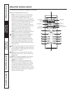
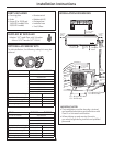
INSTALLATION (cont.)
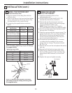
2
Indoor unit
*L1 will be used for neutral
in 115V models.
Outdoor unit
To branch
circuit
Ground
Power supply
115V Models
4-way
terminal
board
Power
connection
cord
Fixing nut
Back of unit
Connecting cover
12
Electrical wires must be secured
with attached strain reliefs.
Indoor unit
Outdoor unit
To branch
circuit
Ground
Power supply
230/208V Models