


19
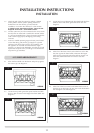
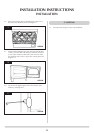
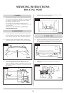
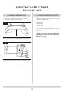
8.1 Turn the gas supply off at the isolation device. Ensure that
the appliance is cold before commencing work on it
8.2 Undo the compression nut from the injector (A) and loosen
the compression nut (B) in the gas valve body. The pipe can
now be positioned out of the way, screw the injector (C)
out of the burner unit. See diagram 13.
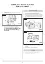
8.3 Reassemble in reverse order, the injector must NOT be
tightened into the burner but be allowed to float to enable
it to line up with the pipe. Turn on the gas supply and
check for leaks.
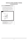
9.1 Open the door and remove the ceramics, placing them
carefully to one side. Undo the two screws in the back of
the firebox and carefully withdraw the bracket. See diagram
14.
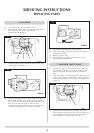
9.2 Disconnect the two sender wires. Undo the two taptite
screws and remove the sensor and the two plastic spacers.
See diagram 15.
9.3 Refit the new sensor ensuring that the plastic spacers are
located between the bracket and the sensor. Refit the leads.
See diagram 16.
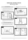
9.4 Feed the cable back through the hole as you replace the
bracket. When the bracket is located correctly it will sit
flush with the back panel without force being required. If
not positioned correctly the bracket will sit at an angle. See
diagram 17.
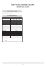
SERVICING INSTRUCTIONS
REPLACING PARTS
8. MAIN INJECTOR
9. GAZCO FLUE SURE SYSTEM
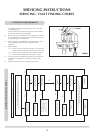
AR1441
AR1442
AR1446
AR1448
AR1452
AR1447
C
B
A
13
14
17
16
15