


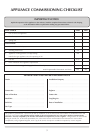

11
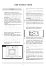
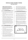
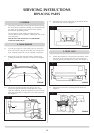
3.5 Check the pull of the flue system by applying a lighted
smoke pellet to the flue system opening. If there is a
definite flow into the chimney, proceed with the
installation, if not warm the chimney for a few minutes.
IF THERE IS STILL NO DEFINITE FLOW, THE FLUE MAY
REQUIRE ATTENTION - SEEK EXPERT ADVICE
3.6 The flue system may now be connected to the stove, ensure
that all joints are sealed with a suitable fire resistant sealant.
It is also recommended that a physical retention method be
used at the flue spigot joint, self-tapping screws being
favoured.
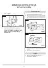
3.7 Connect a suitable pressure gauge to the test point located
on the inlet fitting, and turn the gas supply on. Light the
appliance and check all gas joints for gas soundness. Turn
the appliance to maximum and check that the supply
pressure is as stated on the databadge. Turn the gas off and
replace the test point screw, turn the gas on and check the
test point for gas soundness.
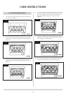
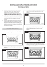
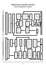
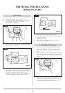
4.1 Place the flame baffle onto the burner and push up against
the rear tray lip. See diagram 4.
4.2 Locate the rear panel against the spacer brackets and slide
down so that it locates on the ledge of the flame baffle. See
diagram 5.
4.3 Locate the front coal between the heat shield and the flame
baffle so that it ends sit flat against the burner skin. See
diagram 6.
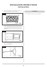
4.4 Place five of the loose round coals on the frint coal so that
they lean against the flame baffle, in between the fingers.
Place the two rectangular against the reflector panels, one
either side, behind the front row of loose coals. See
diagram 7.
4.5 Place four of the loose round coals behind the first row so
that they sit on the fingers, the two outer coals should touch
the rectangular coals. See diagram 8.
INSTALLATION INSTRUCTIONS
INSTALLATION
4. FUELBED ARRANGEMENT
AR0361
AR0360
AR0359
AR0362
AR0363
4
5
6
7
8