


9
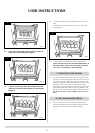
INSTALLATION INSTRUCTIONS
SITE REQUIREMENTS
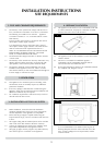
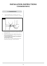
1. FLUE AND CHIMNEY REQUIREMENTS
1.1 The chimney or flue system must comply with the rules in
force, and must be a minimum of 127mm (5”) in diameter.
The following are suitable for use with this appliance.
A) 230mm x 230mm (9” x 9”) conventional brick or stone
built chimney.
B) A precast flue system used in conjunction with vertical
closure plate and flue spigot extention.
C) A metal flue box used in conjunction with a vertical
closure plate and flue spigot extention. The metal flue box
must be constructed to the requirements of BS 715.
NOTE: IF IT IS INTENDED TO FIT THE STOVE INTO AN
EXISTING BRICK CHIMNEY WITHOUT A CLOSURE
PLATE, A 127MM LINER MUST BE USED.
1.2 The minimum effect height of the flue or chimney must be
3 metres (10ft).
1.3 The chimney or flue must be free from any obstruction. Any
damper plates should be removed or secured in the fully
open position, and no restrictor plates should be fitted.
1.4 The chimney should be swept immediately prior to the
installation of the appliance. However, where it can be
seen that the chimney is clean and unobstructed throughout
its entire length, it need not be swept.
2. VENTILATION
2.1 This appliance has a nominal input not exceeding 7.0kw
and therefore, does not normally require any additional
premanent ventilation.
2.2 If however, spillage is detected when commissioning the
appliance, there may be insufficient natural ventilation and
additional ventilation may be required.
2.3 For ventilation requirements it will be necessary to refer to
national and local rules in force.
3. INSTALLATION OF THE GAS SUPPLY
3.1 Before installation, ensure that the local distribution
conditions (identification of the type of gas and pressure)
and the adjustment of the appliance are compatible.
3.2 Ensure that the gas supply is capable of delivering the
required amount of gas, and is in accordance with the rules
in force.
3.3 Soft copper tubing and soft soldered joints can be used but
must not be closer than 50mm to the base of the tray.
3.4 A means of isolating the gas supply to the appliance must
be provided independent of any appliance control.
3.5 All supply gas pipes must be purged of any debris that may
have entered, prior to connection to the appliance.
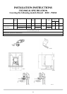
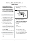
4. APPLIANCE LOCATION
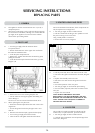
4.1 This appliance must stand on a non-combustible hearth that
is at least 12mm thick, and project a minimum of 50mm
from the base of the stove in all directions.
AR0035
1
4.2 This appliance must not be installed in a room that contains
a bath or shower.
4.3 The stove is not suitable for installation against a
combustible wall; all combustible materials must be
removed from the area behind the stove.
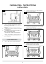
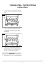
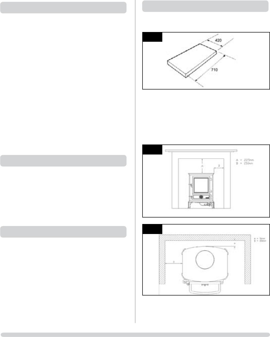
4.4 Ensure that all minimum clearances to combusible materials
are complied with, Diagrams 2 & 2A.
AR0884
2
AR0885
2A
In a non-combustible recess attention must be given to
allowing adequate clearance at the sides and rear of the
stove, so that a spillage test can be performed, and the
controls reached.