11
AR0886
4
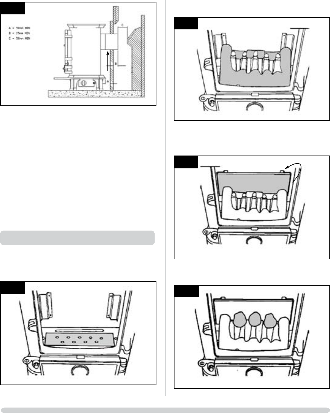
2.7 • Placetheclosureplateagainstthefireplaceopening•
• Ensurethereissufficientoverlaparoundtheperimeterto
allow a fume tight seal to be made
• Cutstraightacrossthetopoftheplateiftrimmingis
required
2.8 • Sealtheplatetotheopeningandthehearthwithsuitable
heat resisting material.
2.9 • Securethespigotextensiontotheengineassemblyand
seal with heat resisting tape or similar
• Positiontheengineassemblyensuringthe50mmrear
clearance is maintained
• Proceedwiththeinstallationasdetailedinpoints2.2to
2.6 above.
2.10 • Securethelipplatetotheundersideofthestovewith
the two bolts provided.
3. FUELBED ARRANGEMENT
3.1 • Placethewhiteceramiccovergasketontotheburner
• Ensuretheholesalignwiththeburnerports,Diagram5.
AR0898
5
3.2 • Placethefuelbedovertheburner,tallestparttowards
the rear of the firebox, Diagram 6
AR0899
6
3.3 • Carefullyfeedtherearpanelintothefireboxandengage
it between the two locating brackets
• Slidethepaneldownbehindthefuelbed,Diagram7
AR0900
7
3.4 • Placethreecoalsequallyspacedontherearofthefuel
bed so they touch the rear panel, Diagram 8
AR0901
8
INSTALLATION INSTRUCTIONS
INSTALLATION


