


Form #43343330
–48– May 08
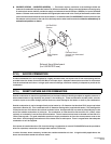
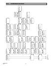
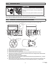
1. Open hinged access panel.
2. Add tubing to connect the air switch tubing P1 + and P2 - with the connector tees and the probes P1+ and P2+.
3. Connect plastic tubing of a digital or inclined water manometer with a 0-2” scale onto the connector tees.
4. Turn heater on and wait until blower motor is activated.
5. Observe air pressure from manometer. This should be higher than the set point indicated below for correct
operation.
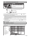
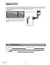
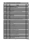
Model
Operating Pressure
PTS/U 40 0.98” W.C. Hot
PTS/U 50 0.98” W.C. Hot
PTS/U 75 0.70” W.C. Hot
PTS/U 100 0.70” W.C. Hot
PTS/U 125 0.39” W.C. Hot
PTS/U 150 0.39” W.C. Hot
PTS/U 175 0.39” W.C. Hot
PTS/U 200 0.39” W.C. Hot
All pressures are with the heater in operation for at least 15 minutes.
23.4) IGNITION SYSTEM CHECKS
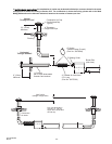
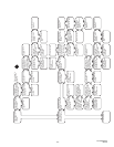
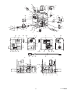
TO CHECK FLAME SENSOR CIRCUIT.
Flame current is the current which passes through the flame from the sensor to ground. The minimum flame
current necessary to keep the system from lockout is 0.7 microamps.
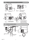
a) Turn off heater at thermostat.
b) Connect a meter (dc microammeter scale) in series with the ground lead as shown in the diagram. Connect the
meter as follows:
Connect the black (negative) meter lead to the electronic control FC- terminal.
Connect the red (positive) meter lead to the electronic control FC+ terminal.
c) Restart the system and read the meter. The flame sensor current must be steady and measure at least 0.7
microamps.
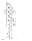
d) If the meter reads less than the minimum or if reading is unsteady:
Make sure burner flame is capable of providing a good rectification signal.
Make sure fasteners securing igniter/sensor are tightened to assure correct positions. DO NOT relocate
igniter/sensor.
Check for excessive (over 1000ºF) temperature at ceramic insulator on flame sensor. Excessive temperature
can cause short to ground. DO NOT relocate igniter/sensor.
Check for cracked ceramic insulator, which can cause short to ground, and replace sensor if necessary.
Make sure that electrical connections are clean and tight. Replace damaged wire.
e) If the meter reads below “0” on the scale, meter leads are reversed. Disconnect power and reconnect meter
leads for proper polarity.
f) Remove microammeter. Return system to normal operation.