


Form #43343330
May 08 –33–
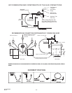
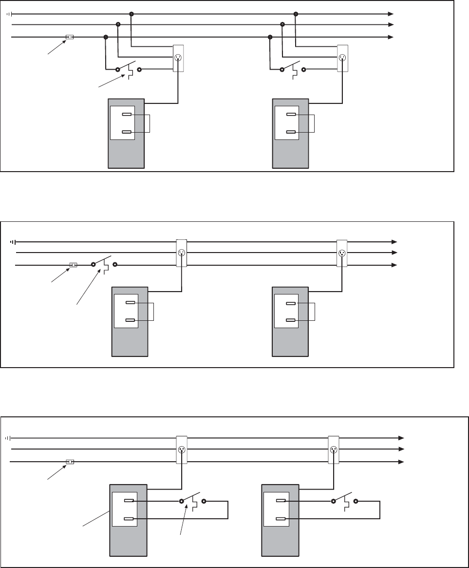
FIELD CONNECTION WIRING DIAGRAMS
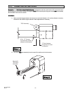
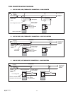
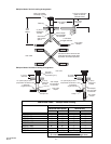
A. LINE VOLTAGE (120V) THERMOSTAT CONNECTIONS – SINGLE HEATER
Burner Control Box
Ground
N Neutral
L1 Hot (120V)
Line voltage thermostat
Continue To
Additional
Heaters
Power Supply
Cord (120V)
Receptacle
Jumper factory
installed for optional
24V thermostat
Fused
Disconnect
switch
TH
C
TH
C
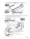
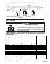
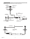
B. LINE VOLTAGE (120V) THERMOSTAT CONNECTIONS – MULTIPLE HEATERS
Burner Control Box
Ground
N Neutral
L1 Hot (120V)
Line voltage
thermostat
Continue To
Additional
Heaters
Power Supply
Cord (120V)
Receptacle
TH
C
Receptacle
TH
C
Jumper factory
installed for optional
24V thermostat
Fused
Disconnect
switch
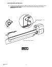
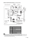
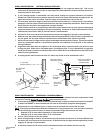
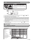
C. LOW VOLTAGE (24V) THERMOSTAT CONNECTIONS – SINGLE HEATERS
Burner Control Box
Ground
N Neutral
L1 Hot (120V)
Line voltage stat
Continue To
Additional
Heaters
Power Supply
Cord (120V)
Receptacle
Remove Jumper factory
installed for 24V thermostat
Fused
Disconnect
switch
Low voltage
(24V) thermostat
TH
C
TH
C